Acowa SPIDER Bedienungsanleitung

1
User manual
ACOWA SPIDER / ACOWA ZOO
August 2019

2
Table of Contents
Content
Table of Contents .............................................................................................................................................. 2
SPIDER................................................................................................................................................................ 4
About SPIDER................................................................................................................................................. 4
Funktions ....................................................................................................................................................... 4
Installation..................................................................................................................................................... 5
Power supply ............................................................................................................................................. 5
Physical measurements............................................................................................................................. 5
Installation environments.......................................................................................................................... 5
Build-in power supply................................................................................................................................ 5
Analog input .............................................................................................................................................. 6
Digital input with the option of 0-10V analog........................................................................................... 6
Digital output............................................................................................................................................. 6
Operation....................................................................................................................................................... 7
Overview.................................................................................................................................................... 7
The red button........................................................................................................................................... 7
SPIDER diodes............................................................................................................................................ 8
Menu structure for the 2,4” OLED Display................................................................................................ 9
HMI display................................................................................................................................................ 9
I/O module................................................................................................................................................... 10
ACOWA ZOO Configuration Tool..................................................................................................................... 11
Connecting to a PC ...................................................................................................................................... 11
USB connection ....................................................................................................................................... 11
TCP Connection ....................................................................................................................................... 11
ACOWA ZOO Installation............................................................................................................................. 11
Driver installation .................................................................................................................................... 11
Program installation ................................................................................................................................ 11
ACOWA ZOO................................................................................................................................................ 13
Overview.................................................................................................................................................. 13
Function buttons ..................................................................................................................................... 13
Settings selection..................................................................................................................................... 14
SPIDER details.......................................................................................................................................... 15

Input and output Settings............................................................................................................................ 15
Analog Input (AI1).................................................................................................................................... 15

3
Digital Inputs (I1–I6) ................................................................................................................................ 17
Digital output............................................................................................................................................... 19
Device settings / advanced settings ............................................................................................................ 22
Reports and alarms:................................................................................................................................. 22
Reverse Comm:........................................................................................................................................ 22
Show Status ................................................................................................................................................. 24
Online status............................................................................................................................................ 24
Applications................................................................................................................................................. 25
Pump control:.......................................................................................................................................... 25
Flow interface:......................................................................................................................................... 25
Additional Options:.................................................................................................................................. 26
Ground water lowering: .......................................................................................................................... 26
Monitoring:.............................................................................................................................................. 27
Compressor control:................................................................................................................................ 27
Register list quick-guide .............................................................................................................................. 28

4
SPIDER
About SPIDER
SPIDER is a universal control with functions for pump control, data collection, alarm management,
groundwater lowering etc.
SPIDER is developed and produced in Denmark. SPIDER complies with all specifications regarding
placement of electronic components in harsh environments.
Funktions
•Advanced 1 and 2 pump control with empty/fill function and internal pump alternation.
•Build-in GSM/GPRS Modem.
•Multi-protocol: Modbus RTU/TCP & COMLI. SPIDER auto-detects the protocol used by the SCADA
system.
•Click connection for a joystick-equipped graphic 2,4” OLED display directly onto SPIDER.
•Possibility to connect a 7” color touch-sensitive display via a serial HMI interface.
•Validated flow calculation where the pumps capacity is dynamically calculated.
•Status words function that can take a failed pump out of operation.
•Emergency control function via a float switch when a pressure transmitter fails.
•Indication of required pump service where SPIDER informs that a pump has reduced capacity.
•Built-in power bank that maintains control during power failures and sends an alarm to SCADA.
•Daily running of pumps so they do not seize after long idle periods.
•Daily depth pumping to avoid top sediment layer.
•Choice of various start levels to prevent sediment accumulation at liquid entrance point.
•Configuration of SPIDER via ACOWA ZOO software, both locally (Micro USB cable) or via server setup.

5
Installation
Power supply
SPIDER must be connected to a supply voltage according to the specifications below.
Voltage supply
230 VAC +10% / -20%
Frequency
50/60Hz
Input current consumption
0,004 -> 0,06A
Startup current
<10A
Own consumption
Max. 10W
Fuse
≤250mAT
SPIDER is equipped with a built-in Power bank and can send voltage
failure alarms when the primary power supply disappears.
The SPIDER Power bank (the two green high capacity capacitors) is
located on the bottom of the top print.
WARNING! Do not disassemble device until Power bank is turned off.
Physical measurements
For the installation of the SPIDER controller, the following specifications may be required.
SPIDER can be mounted on a standard 35mm DIN-rail.
Dimensions
L = 87mm x H = 90mm x W = 62mm
Weight
250g
Cable connection
0.5 –2,5 mm2
Vibrations (sinus shaped)
10-500Hz, 1G
Installation environments
SPIDER must not be installed in direct sunlight
Humidity
10% - 95% non-condensing
Operation temperature
-20°C to +50°C
Storage temperature
-20°C to +60°C
Maximum operation elevation
Max. 2000m above sea level
Free fall drop
30cm
Enclosure class
IP20
Start-up time total
20-120 sec. (depending on the GSM network)
Build-in power supply
SPIDER has an internal power supply designed for supplying sensors and input and output signals. Power
supply output + V:
Output voltage
24 V DC
Output current
Max. 100mA
Tolerance
+ / - 20%

6
Analog input
SPIDER is designed with one analog input 0 ... 20 mA / 4 … 20 mA.
Numbers of analog mA inputs
1
Electrically isolated
No
Measuring range
0 / 4 –20mA
Input impedance
Approx. 100 Ω
Measuring accuracy
+/- 1% af FS
Signal area
0-24mA / 0 –30 V DC
Signal frequence
Max. 100 Hz
Kabel / signal lenght
Max. 100m
Digital input with the option of 0-10V analog
SPIDER has 6 digital inputs, all of which can be selected as 0-10V analog voltage inputs.
Numbers of digital inputs
6
Electrically inslated
No
Digital signal
Low < 5 V / < 1 mA
High> 12 V / > 4 mA
Analog measuring range
0 –10 V DC
Analog signal impedance
Approx. 20KΩ
Measuring accuracy
+/- 1% of FS
Signal range (min / max)
0 –30 V DC
Signal f frequence
Max. 100 Hz
Kabel / signal lenght
Max. 100m
Digital output
SPIDER is equipped with 4 digital relay outputs.
Numbers of digital outputs
4
Electrically isolated
Yes
Insulation voltage
4 KV
Relay type
Relay output
Kabel / signal lenght
Max. 100m
Relay NO #11 og #21
Constant load
max. 10 A @ 230Vac - AC1
max. 500 W @ 230Vac - AC3
max. 1 A @ 48 VDC
max. 10 A @ 24 VDC
Minimum current
5 mA @ 10 V
Max. Start-up current
18A
Switch speed
Max. 1 Hz
Relay NO #31 og #41
Constant load
max. 2 A @ 230Vac - AC1
max. 100 W @ 230Vac - AC3
max. 1 A @ 30 VDC
Minimum current
5 mA @ 10 V
Max. Start-up current
6A or 10A @ 20 ms
Switch speed
Max. 10 Hz

7
Operation
Overview
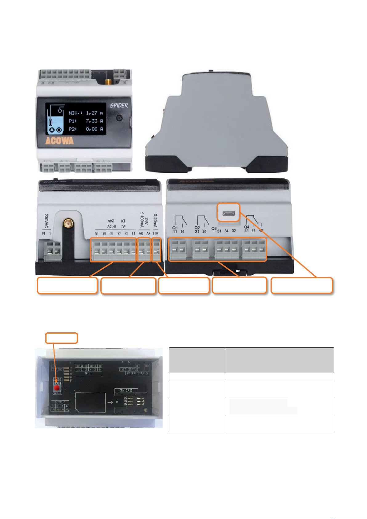
The red button
SPIDER has a red button on the print next to the SIM card where it is possible to restart / reset SPIDER.
The red button on the top print has the following functions:
The number of
activations within
a 5 sec. range.
Function
1
Reset modem
3
Enable / disable display interface
(baud rate 57600 bps)
5
Enable HMI interface
(baud rate to 38400 bps)
Hold the button
in for 10 sec.
SPIDER restarts. Used in connection
with firmware-update or similar.
Digital Inputs
Digital outputs
Analog inputs
USB connection
Power supply

8
SPIDER diodes
Status
Flashes every 5 seconds: status to
indicate that the device is working.
Double flash means that the HMI
interface / oled display is enabled.
Net-status
Flashing fast (2 times per second):
modem is not connected to the GSM
mast.
Flashes slowly (once per second) and is
connected to the GSM mast.
Modem-status flashes when a modem is connected to the GSM mast and a signal strength is detected.
Display
SPIDER comes with two different types of displays but can also work without a display.
Display for direct mounting on SPIDER is a 2.4 "OLED display. The display has different screen settings and
can be operated with the joystick on the right side.
There is a pause screen which disables the normal screen display after 5 minutes. After this it goes to the
screen saver picture where level is displayed in different places on screen.

9
Menu structure for the 2,4” OLED Display
HMI display
SPIDER can also be delivered with a larger 7” HMI display where a larger graphic image can be designed. It
is possible to design customized graphics.
A serial overprint is required. This is easily clicked on the SPIDER as well as cable sets and HMI display.
SPIDER HMI kit incl. cable sets, SPIDER serial print incl. 1.5m cable set

10
I/O module
For connections of further signals, it is possible to connect an I/O module with multiple digital and analog
inputs.
Dieses Handbuch passt für folgende Modelle
1
Inhaltsverzeichnis
Beliebte Steuereinheit Handbücher anderer Marken

Festo
Festo Compact Performance CP-FB6-E Stücklistenhandbuch

Elo TouchSystems
Elo TouchSystems DMS-SA19P-EXTME Bedienungsanleitung

JS Automation
JS Automation MPC3034A Bedienungsanleitung

JAUDT
JAUDT SW GII 6406 Series Kurzanleitung

Spektrum
Spektrum Air Module System Bedienungsanleitung

BOC Edwards
BOC Edwards Q Series Bedienungsanleitung