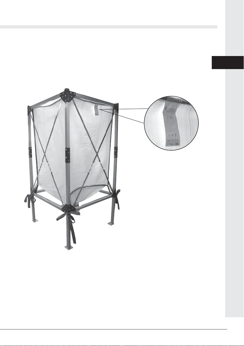
Advance acoustic TEXSILO 120 Kurzanleitung zur Einrichtung

13
ASSEMBLY, USE AND
MAINTENANCE MANUAL
Fuel storage tank
TEXSILO 120


3
• Type: Fuel storage tank
• Model: TEXSILO 120
• Revision 1.0.2
FUEL STORAGE TANK
TEXSILO 120
INSTRUCTION MANUAL
17/05/22 Rev:1.0.2
1 INTRODUCTION 4
1.1 Use of this manual 4
2 WARNINGS 4
3 INSTALLER’S RESPONSIBILITIES 5
4 CONSTRUCTION FEATURES 5
5 WEIGHTS AND MEASURES TABLE 5
6 CHECK OF PACKAGING CONTENT 6
7 ASSEMBLY EQUIPMENT 6
8 IDENTIFICATION PLATE 7
9 PROPER USE OF THE PRODUCT 8
10 INSTALLATION 8
10.1 Place of installation 8
11 ASSEMBLY 9
12 START UP AND USE 15
13 MAINTENANCE AND END-OF-LIFE 15
13.1 End-of-life 15
14 SAFETY REQUIREMENTS FOR FUEL STORAGE TANKS 16
15 WARRANTY 17
16 CERTIFICATION 18
INDEX

Fuel storage tank
4
17/05/22 Rev:1.0.2
1 INTRODUCTION
Dear customer,
the manufacturer would firstly like to thank you for the choice you made in buying an of our product,
whose technical features will certainly meet Your needs.
Our products have been designed and manufactured in total compliance with the current regulations, by
choosing the best materials to obtain durability and ease of use of the product.
We ask you, therefore, to read this manual carefully and completely, following strictly the instructions
contained herein.
1.1 Use of this manual
The instruction manual is a document drawn up by the manufacturer and is part of the product: it
integrates the specific rules of application and general rules for people, animals and objects safety. In the
event that the product is resold, handed over, rented or sold to others, it must always be accompanied
by this manual; therefore, it is recommended to use and keep it with care for the entire operative life of
the product.
The main objective of this manual is to make known the proper and safe way to use the equipment.
No part of this manual may be reproduced, copied, or shared in any way, without the written permission
of the manufacturer.
The manufacturer reserves the right to make improvements or modifications to this manual
and to the equipment at any time, without obligation to advise third parties.
2 WARNINGS
• Do not use the machine for any improper use.
• Do not let children near the machine.
• This unit must not be used by people (including children) with reduced physical, sensory or mental
capabilities, or with lack of experience and knowledge, unless they are supervised or instructed in the
use of the unit by a person responsible for their safety.
• Use only original spare parts.
• In order to be able to operate easily on the tank, you must leave all around and above it a space of at
least 50 cm which must be completely free from any obstacle.
• This tank can contain only wood pellet and olive pomace
• Before proceeding to the first filling of the tank check that it is properly installed with a spirit level and
that all fixing screws are tight.
• After the first filling, tighten all screws again.
• It is forbidden to add other loads or weights to the tank in addition to the one of the fuel contained
therein.
• Never use the tank structure as a carrier or fixing element for any other support or equipment.
• It is necessary to ventilate the environment where the tank is installed during loading.
The manufacturer declines any liability or guarantee, if the buyer or anyone makes changes or even
minor modifications to the purchased product.

5
English
17/05/22 Rev:1.0.2
4 CONSTRUCTION FEATURES
• painted steel structure
• high-strength polypropylene fabric
• Ø 650 mm upper filling pipe
• Ø 260 mm lower extraction poin
5 WEIGHTS AND MEASURES TABLE
Article
AP3450.12.12
Model
Texsilo 120
Weight
Kg 74
Width and depth Cm 120
Height Cm 234
Fuel bag volume mС1,9
Bag safety factor 6:1
Fabric gr/m2200
AnƟstaƟc fabric Ɵpe B
Useful capacity Ton 1,2
Maximum capacity Ton 1,4
OperaƟng temperature min/max
C° -10 ÷ +50
Degree of humidity min/max % 30 ÷ 95
3 INSTALLER’S RESPONSIBILITIES
To ensure proper operation of the product, follow these guidelines:
• Only perform the activities described in these instructions
• Perform all activities in accordance with applicable regulations
• Explain to the user the operation and use of the product
• Explain to the user how to maintain the product
• Report to the user the potential dangers related to the use of the product

Fuel storage tank
6
17/05/22 Rev:1.0.2
6 CHECK OF PACKAGING CONTENT
After opening the packaging, make an inventory of what you have received, which should consist of:
Check that the product corresponds to the one ordered and that no transportation damage is evident.
Should this not be the case, please contact immediately the seller.
7 ASSEMBLY EQUIPMENT
10 13 17 mm
MANUALE TECNICO
x 8
x 8
x 8
x 8
x 8
x 4
x 4 x 4
x 8
x 1
x 1
x 1
x 1
x 16 x 16 x 72 x 4
x 4

7
English
17/05/22 Rev:1.0.2
8 IDENTIFICATION PLATE
Do not remove or damage the identification plate.

Fuel storage tank
8
17/05/22 Rev:1.0.2
9 PROPER USE OF THE PRODUCT
The fuel storage tank has been designed to be installed for the pneumatic transport of pellets or other
biomass fuels with a medium-fine size.
This product is suitable for the storage of biomass fuel such as pellets, olive pomace, corn.
It cannot store substances that are not biomass fuels and that have excessive or too fine dimen-
sions, sharp or abrasive surfaces or that are easily compactable.
The tank is not predisposed to be loaded by pressure blowing of the fuel inside it, therefore it should not
be loaded by tanker, but only manually or mechanically and only by fall from the loading inlet on the top.
The loading of the tank can be carried out by manual filling of fuel contained in bags or big bags.
Fuel extraction can be made both from the lower and the upper opening by one of the devices in the
catalog.
10 INSTALLATION
It is necessary to leave a free space of adequate size all around the product, in order to permit any
repair, maintenance or inspection operation.
Only qualified technical personnel are authorized to carry out installation, use and maintenance of the
product. All operations must be performed adopting accident prevention regulations, in accordance
with safety warnings (EN 6024-1).
In the event of damage, anomalies or defects of the product, do not install and contact your retailer.
10.1 Place of installation
Below are the main rules to follow for proper installation:
• It is the responsibility of the installer to check always the suitability and characteristics of the product
installation site
• It is the responsibility of the installer to comply with fire prevention regulations
• It is the responsibility of the installer to ensure that the location and the placement of the tank within it
ensures compliance with the applicable accident prevention regulations
• The tank must not be exposed to atmospheric agents and must not be installed in locations subject to:
high humidity, possible flooding, high temperatures, presence of corrosive gases or dusts
• The floor on which the magazine is positioned must be tested to stand, at the base of each leg, one
quarter of the total weight of the tank at full load (approximately 400 kg.).
• The positioning of the tank must guarantee around and above it a minimum free space of 50 cm and
the absence of obstacles, even if temporary
• The magazine fabric should never be in contact with wet or rough walls or surfaces.

9
English
17/05/22 Rev:1.0.2
2- Position the upper and lower joints on the four pillars already assembled using three TTQ M 8
screws as shown in Figures 2.1 and 2.2
11 ASSEMBLY
Carefully clean the floor in the work area before starting the tank assembly phases.
Consider that once the tank is fully assembled, it will be difficult to move it, so it is advisable to
carry out the mounting steps near the site where it will be installed.
Make sure that the ceiling of the room in which the tank is assembled and installed has a height
that allows easy loading of the fuel from the upper inlet, it is advisable at least a minimum height
of 280 cm.
1- Proceed with the construction of the steel frame by assembling the two parts that make
up each pillar with four TTQ M 8 screws, using the appropriate jaws as junctions as shown in
figure 1
Lower joint
Figure 2.1
Figure 1
Figure 2.2
Upper joint

Fuel storage tank
10
17/05/22 Rev:1.0.2
4 - Fit the two pillars previously assembled using a beam and fixing it with 4 TTQ M 8 screws
on the lower joints as shown in figure 4.
Now install also the upper beam by fixing it with four TTQ M 8 screws to the relative joints,
taking care to install in the same time also the inner reinforcement plates as shown in figure 5
3-Insert the lower support at the base of each pillar fixing it using two washers and a cot-
ter pin as shown in figure 3.1, then fold the two sides of the cotter pin as shown in figure 3.2
Figure 3.1
Cotter pin
insertion
Cotter pin
fixing
Figure 4 Figure 5
Figure 3.2
Inhaltsverzeichnis
Beliebte Lagerung Handbücher anderer Marken

Spectra Logic
Spectra Logic T-Series Spectra T50e Bedienungsanleitung

Panasonic
Panasonic LKM-F931-1 Bedienungsanleitung

Tabernus
Tabernus Enterprise Erase E2400 Bedienungsanleitung

Rocstor
Rocstor COMMANDER 3F series Bedienungsanleitung

HP
HP P9000 Bedienungsanleitung

Western Digital
Western Digital Ultrastar Data60 Bedienungsanleitung


