AERA EVO-MODULAR Series Bedienungsanleitung

User’s
Manual EVO-MODULAR
AIR HANDLING UNITS

2
Contents
General Information.................................................3
Transport Installation ............................................5
Installation and Assembly......................................7
Installation of Components and Accessories........13
Electrical Connection..........................................18
Commissioning and Maintenance........................24

3
General Information
Foreword
General
EVO-M air handling units (AHUs) have been designed and manufactured in accordance with the CE machine directive. In
order to guarantee safe operation and use of the unit, please carefully read and observe the instructions in this document and
pay special attention to the warnings that apply to this unit. Any modifications in the design and/ or installation of the AHU
that are carried out without discussion with AERA and without advance written agreement will result in the loss of the right to
any warranty claims and any claim for injury to personnel as a result of these modifications. All work must be carried out by
sufficiently trained personnel.
Warnings and cautions
Warnings and Cautions appear at appropriate sections throughout this manual. Your personal safety and the proper operation
of this machine require that you follow them carefully. The constructor assumes no liability for installations or servicing performed
by unqualified personnel.
WARNING!: Indicates a potentially hazardous situation which, if not avoided, could result in death or serious injury.
CAUTION!: Indicates a potentially hazardous situation which, if not avoided, may result in minor or moderate injury. It may also
be used to alert against unsafe practices or for equipment or property-damage-only accidents.
Safety Considerations
To avoid death, injury, equipment or property damage, the following recommendations should be observed during equipment
operation:
1. The units are suitable for ambient air temperature between -20°C and +60°C and for air flow temperature between -20°C
and +40°C. Different conditions need written confirmation from the manufacturer.
2. Care should be taken by the user to prevent frost in coils. For ambient temperatures below 0C make sure that water inside
the cooling coil is removed during winter and a minimum of 25% Ethylene Glycol is added to heating water circuit.
3. Components - Some OEM products have specific manufacturer’s service instruction documents. These are delivered with
the Air Handling Unit. In this case, the indications in the OEM manual are valid and the service handbook in hand has only
general or complementary character for the relating components.
4. Liquid and gas storage -Maximum working pressure for all coils is 15bar. In case of coil connections to higher working
pressures, any warranty relating to coil tightness and personnel safety is excluded.
5. Tubing filled with mediums with very high or low working temperatures are to be insulated with suitable materials to avoid
burn or scald injuries caused by contact.
6. As fire prevention, fire dampers are to be provided where ducts cross firebreaks. Local fire prevention code is to be observed
carefully.
7. In case of external electrical heater usage, the operation of the heater and AHU must be interlocked and appropriate safety
components are used in the electrical circuit.
To avoid death, injury, equipment or property damage, the following recommendations should be observed during maintenance
and service visits:
1. The maximum allowable pressures for system leak testing on low and high pressure side are given in the chapter “Installation”.
Always provide a pressure regulator.
2. Disconnect the main power supply before any servicing on the unit.
3. The Air Handling Unit control system must guarantee that in case of breakdown or power interruption during maintenance
or repair work, the unforeseen start-up of a shut off unit is impossible.
4. Service work on the refrigeration system and the electrical system should be carried out only by qualified and experienced
personnel.
5. For inspection on the Air Handling Units and to avoid risks, the units surroundings are to be sufficiently lighted.
6. Heat exchangers filled with refrigerants must be serviced by specialized personnel. Waste disposal or recycling of dangerous
refrigerants must done in accordance with all international, national, and local regulations.
7. Where units are installed in areas with high temperature and/or high humidity, the risks of external condensation on the
casing must be considered.

4
General Information
Reception
On arrival, inspect the unit before signing the delivery note.
In case of visible damage: The consignee (or the site representative) must specify any damage on the delivery note, legibly sign
and date the delivery note, and the truck driver must countersign it. The consignee (or the site representative) must notify AERA.
And send a copy of the delivery note. The customer (or the site representative) should send a registered letter to the last carrier
within 3 days of delivery.
Warranty
Warranty is based on the general terms and conditions of the manufacturer. The warranty is void if the equipment is repaired
or modified without the written approval of the manufacturer, if the operating limits are exceeded or if the control system or the
electrical wiring is modified. Damage due to misuse, lack of maintenance or failure to comply with the manufacturer’s instructi-
ons or recommendations is not covered by the warranty obligation. If the user does not conform to the rules of this manual, it
may entail cancellation of warranty and liabilities by the manufacturer. Electrical motors are factory-tested and properly run when
leaving the factory. Any wiring faults on motors will cause damage for which AERA cannot be held responsible.
• The control package ( either bought from AERA as an accessory or sourced from a third party) must include frost protection
routines and components to prevent freezing damage of internal components (coils, heat recovery devices, humidifiers, …)
• Electrical connections may become un-tightened during transport. All electrical connections should be checked and re-ti-
ghten prior to commissioning. All electrical connections shall be made according to the wiring diagrams provided on the
components or in provided documents. Warranty is not valid if electrical components are not connected properly.
• When the unit use a medium (water/ refrigerant) with a temperature below than +2°C, The unit controls should be designed
in order to protect the exchanger against freezing. AERA cannot be held responsible for damages coming from freezing /
de-freezing operation.
• The warranty does not cover overheating due to wrong use or improper control of electric heaters.
• Dismantling or changing the units and/or components without AERA approval or assistance will invalidate the warranty.
• EVO-M units have been manufactured according to the selections and drawings provided with the order: AERA cannot be
held responsible for eventual non compliance to original specifications or specific requirements outside the order.
• In order to avoid fan motor overloading, the units shall be started with filters and other components fitted correctly, the du-
ctwork connected to the units and the access doors closed.
• Make sure the units work at design (Air flow/Pressure) conditions. The sound levels of the units can vary a lot depending of
the fan speed, the filter conditions or the actual duct pressure drops. Also, the given sound levels can be highly affected by
the installation method, the peripheral components, the ductwork and the acoustic characteristics of the building/room.
• The units must be controlled in order not to exceed the maximum or minimum differential pressure drops on plate heat ex-
changers indicated in the technical data sheets. The efficiency of the exchanger may drop significantly in higher / lower air
volumes and/or uneven air flows.
Maintenance Agreement
It is strongly recommended that you sign a maintenance contract with your local Service Agency. This contract provides regular
maintenance of your installation by a specialist in our equipment. Regular maintenance ensures that any malfunction is detected
and corrected in good time and minimizes the possibility that serious damage will occur. Finally, regular maintenance ensures
the maximum operating life of your equipment. We would remind you that failure to respect these installation and maintenance
instructions may result in immediate cancellation of the warranty.

5
Transport Installation
Storage and preventive maintenance
In case of external storage, units must be protected from adverse weather conditions. With internal and external storage, the
unit must also be protected against everyday damage. To avoid defects on the bearings, the fans and the motors must be
manually turned every month. If the units are not running for more than 18 months, the grease in the bearings must be changed.
When possible, all electrical equipment and fan belts should be removed and stored separately in dry atmosphere.
In case of long term storage, belts shall be removed in order to avoid stress on the bearings.
Off loading and handling
EVO-M units are supplied in section modules, or as a complete unit, in accordance with the relevant assembly drawings.
Any necessary use of force during unloading or movement of the units must only be applied via the unit base frame or the
shipping pallet.
The unit unloading and handling can be carried out easily with the use of a forklift or crane. For sections lighter than 1000 kg,
the unit can be lifted from the transport lugsb delivered separately.
Figure 1 - Crane operation procedure
1. Do not stand on the units. If this is unavoidable ensure a more
even weight distribution by the use of boards.
2. Use battens to prevent damage of the top and sides of the
units.
The forks must only be applied under the unit base frame and
not against it.
Note: The lift point should be as near as possible to the centre
of gravity. The centre of gravity of each section is located at the
centre of the unit length, with the exception of the fan sections
for which the centre of gravity is located towards the motors (see
Figures 2 and 3).
CAUTION! Never lift the units by the heat exchanger connections
or by any other projections. Do not tilt the fan module to avoid
possible impingement on the dampers.
Sections can be delivered provided of feet, pallets done by
wooden blocks positioned on each corner, base frame, base
frame base provide of fork holes.
In the case of section is provided of base frame without any fork
holes or without feet, insert the fork of the lift below the section
lifting it by a lever action. In this case, the bar must only bear against the base frame or profile (see Figure 2).
1 2 3
Figure 2 Figure 3

6
Transport Installation
With larger units, the use of several forklift may be required.
When rigging the unit by crane, follow these guidelines:
1. If lifting holes are provided on the unit base frame, sling spreader bars (see Figure 1, part 3).
2. If lifting holes are not provided, see Figure 1 part 4
3. If, as option, lifting points (eye bolts) are provides, crane belts can be connected directly to them.
4. The minimum rated lifting capacity (vertical) of each sling and spreader bar should be no less than the shipping weight
5. The unit must be lifted with care, avoiding shock load by lifting the unit slowly and evenly.
6. All lifting points in one axis of the unit must be used when offloading and moving the unit.
7. Slings are to be provided by the rigger and attached to all lifting points.
CAUTION! Loading, unloading and removal of single sections have to be carried out by employing means able to support the
unit weight indicated in the technical sheet. Ensure that the belts do not damage the top surface of the unit structure using
proper devices.
Note: Units fitted with base frames may be moved on roller trolleys or tubular rollers (see Figure 4).
CAUTION!
Supportıng and lifting under the cross beams or coils is prohibited. No horizantal transport devices must
be placed under this frame section such as pallet lifters or the forks of fork lift trucks.
7
Installation and Assembly
Installation and Assembly
You will find information regarding the assembly and installation of the unit.
This may only be carried out by specialists with the necessary knowledge of relevant accident
prevention regulations and other standard regulations relevant to health and safety in the workplace,
based on their training and experience.
The unit should be installed in such a way that it is accessible only to technical personnel with the
appropriate authorisation and training. The unit may only be assembled in accordance with the
application shown in the technical information supplied with the unit.
The units must not be stacked with other components that are not part of the unit.
This is only permissible if the necessary load-bearing capacity has been specially incorporated into
the units delivered from AERA
When connecting the duct it must be ensured that no foreign materials can enter the unit. If necessary,
a suitable wire mesh guard can be installed by the third party at the opening on the discharge/intake
side of the unit.
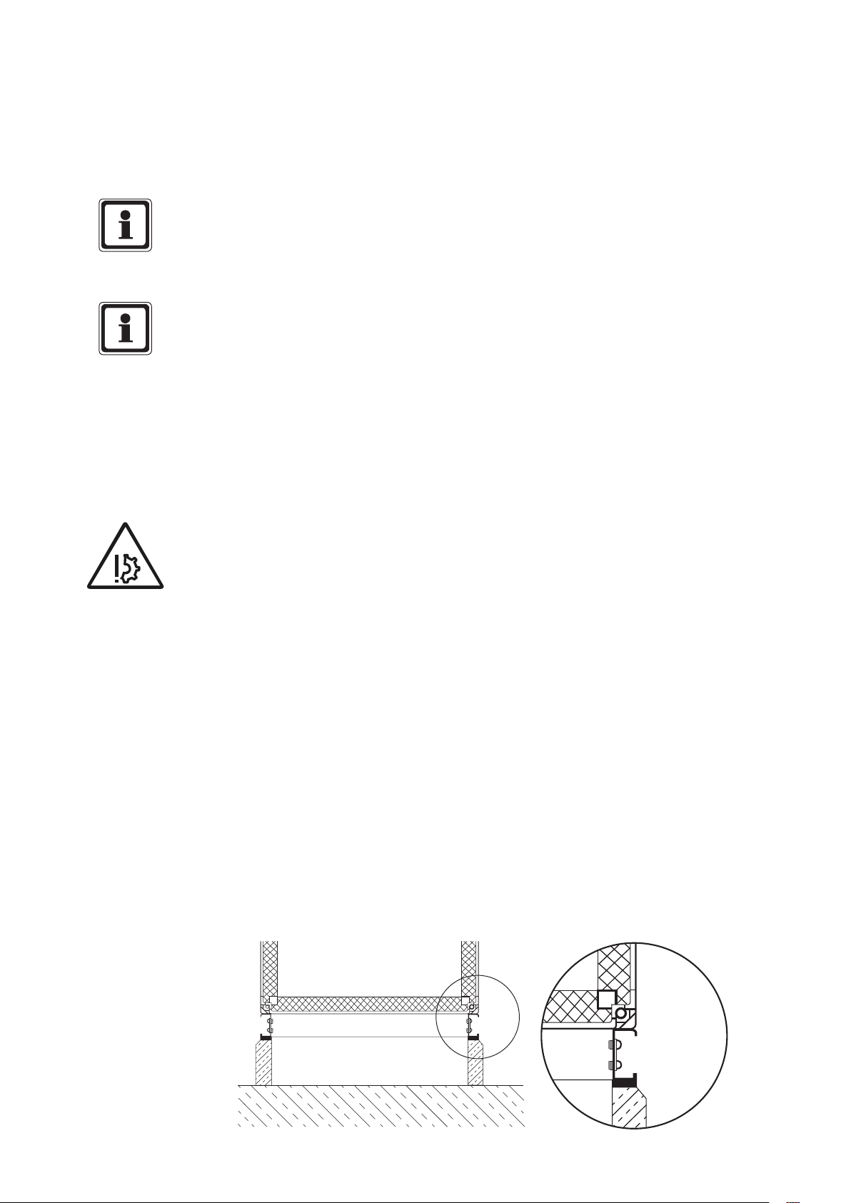
DAMAGE TO THE UNIT!
During installation of EVO-M units special care must be taken to ensure that no loads are applied to
the floor panels. During assembly work suitable measures should be taken to ensure that any loads
are spread across the bottom profiles (e.g. using grid walkways).
Installation
Installation location
The unit must be installed at a location that fulfils the following requirements:
– The substructure must be level and stable.
– The maximum deflection of the substructure may not exceed 4 mm per metre.
– In units where a condensate drain is installed, the height of the substructure must be at least the
same as to the required siphon height (see siphon).
– Make sure that no damage to the installation location or the environment can be caused by loose
components.
- In order to be able to remove fans, heat exchangers, droplet eliminators, etc. and also perform
servicing and maintenance, a minimum clearance of one unit width must be maintained on the
operating side.
- A minimum clearance of 600 mm between the rear of the unit and the wall must be maintained if
the internal dividing joint connectors cannot be used due to the unit configuration.
Heigh adjustment
Figure 5: Installation location

8
Installation and Assembly
Minimum clearances
• In order to be able to remove fans, heat exchangers, droplet
eliminators, etc. and also perform servicing and maintenance, a
minimum clearance of one unit width must be maintained on the
operating side.
• A minimum clearance of 600 mm between the rear of the unit and
the wall must be maintained if the internal dividing joint connectors
cannot be used due to the unit configuration.
Foundation construction for outdoor installation (weatherproof, roof frame)
NOTE!
EVO-M units for outside installation are not a substitution for roof! In compliance with prEN 13053 and
VDI 3803 it is not allowed to use surfaces of weatherproof units to support parts of a building or in a
similar way substitute a roof.
• Instructions for „Foundation construction for indoor installation“ on page 23 should be applied.
• If the unit has fresh air intake and discharge air make sure that the ducts are long enaugh so that
the discharge air is not by-passed to fresh air intake.
• Choose an installation location where the fresh air intake will not be facing the main wind
direction.
• In areas where there is a heavy amount of snowfall, the unit must be installed in a location where
its operation will not be affected by snow. A suitable height for the subconstruction must be
selected.
• If the unit is to be mounted on a roof, then the load-bearing capability of the roof and its
supporting structure must be checked. Consult a structural engineer if necessary.
• The roof edge below the unit, as well as ducts and other roof openings must be performed
waterproof by others.
• The roof frame must be insulated to prevent condensation. For information on installation, see
„Preparing installation of roof“ on page 30.
600 BB
Figure 6-1: Foundation construction on steel supports by others
Figure 6: Foundation construction on
steam beam by others

9
Installation and Assembly
NOTE
Particular care must be taken to ensure compliance with the precise dimensions of roof openings and
to ensure that the foundation is level.
Structure-borne sound attenuation
In order to reduce the transfer of vibrations from the unit to the supporting structure, anti-vibration
mounts and structure-borne sound attenuating mats must be installed.
– We recommend that the foundation is isolated from the unit using rubber plates, for example, where
the unit is installed on level ground and no special structure-borne sound isolation requirements
exist.
– We recommend the use of commercially available spring elements for ceiling mounting.
– For very special acoustic requirements please consult an acoustics engineer to select the most
suitable structure-borne sound attenuation method.
Assembling the unit
NOTE
For detailed information, please refer only to the documentation enclosed with the unit. Data sheet,
installation instructions, small parts and accessories supplied loose can be found in the unit part
specified in the parts list.
DAMAGE TO THE UNIT!
Fittings/attachments etc. not provided by the manufacturer that could cause a leak must not be
mounted on the walls or frame of the unit. The unit’s operability must be maintained.

10
Installation and Assembly
Removing transportation lugs/device/locks
• All transportation lugs/devices/locks marked yellow on and in the unit must be removed prior to
assembly.
• Remove the transportation locks on the fan.
• The transportation lugs on the roof must be removed.
• Remove the screws on the end panels and secure the supplied M8 x 70 screw.
• Remove the lug, screw and bushing at the dividing joint, then secure the supplied M8 x 30 screw.
NOTE!
Because of danger of collision with transport lugs - externally mounted dampers/louvres, flexible
connections are partially supplied loose. These components are field-mounted and sealed by others.
NOTE
Transportation lugs/device must not be used to suspend the units on a permanent basis.
Transportation lugs/device may be used only once.
Figure 6-2: Transport lugs – roof, end wall and
dividing joint
Dieses Handbuch passt für folgende Modelle
1
Inhaltsverzeichnis
Andere AERA Luftaufbereiter Handbücher