
Ametek Land NIR Series Bedienungsanleitung

NIR Thermal Imager
Near-Infrared Thermal Imager
Installation Guide
Issue 10
11 July 2017
Publication No. 806110
Language: English
Copyright © 2017 Land Instruments International
Health and Safety Information
Read all of the instructions in this booklet - including all the WARNINGS and CAUTIONS
- before using this product. If there is any instruction which you do not understand, DO
NOT USE THE PRODUCT.
Safety Signs
WARNING
Indicates a potentially hazardous situation which, if not avoided, could result in death or
personal injury.
CAUTION
Indicates a potentially hazardous situation which, if not avoided, could result in minor or
moderate injury to the user or users, or result in damage to the product or to property.
NOTE
Indicates a potentially hazardous situation which, if not avoided, could result in damage or the loss of
data.
Signs and Symbols used on equipment and Documentation
Caution, risk of electric shock.
Caution, attention to possibility of risk of damage to the product, process or surroundings. Refer
to instruction manual.
Caution, hot surface.
Protective Conductor Terminal.
Observe precautions for handling electrostatic discharge sensitive devices.
Equipment Operation
Use of this instrument in a manner not specied by Land Instruments International may be hazardous.
Read and understand the user documentation supplied before installing and operating the equipment.
The safety of any system incorporating this equipment is the responsibility of the assembler.
Protective Clothing, Face and Eye Protection
It is possible that this equipment is to be installed on, or near to, machinery or equipment operating at
high temperatures and high pressures. Suitable protective clothing, along with face and eye protection
must be worn. Refer to the health and safety guidelines for the machinery/equipment before installing
this product. If in doubt, contact Land Instruments International.
Electrical Power Supply
Before working on the electrical connections, all of the electrical power lines to the equipment must
be isolated. All the electrical cables and signal cables must be connected exactly as indicated in these
operating instructions. If in doubt, contact Land Instruments International.
Storage
The instrument should be stored in its packaging, in a dry sheltered area.
Unpacking
Check all packages for external signs of damage. Check the contents against the packing note.
Lifting Instructions
Where items are too heavy to be lifted manually, use suitably rated lifting equipment. Refer to the
Technical Specication for weights. All lifting should be done as stated in local regulations.
IMPORTANT INFORMATION - PLEASE READ

Contact Us
UK - Droneld
Land Instruments International
Tel: +44 (0) 1246 417691
Email: [email protected]
Web: www.landinst.com
USA - Pittsburgh
AMETEK Land, Inc.
Tel: +1 412 826 4444
Web: www.ametek-land.com
China
AMETEK Land China Service
Tel: +86 21 5868 5111 ext 122
Email: [email protected]
Web: www.landinst.com
India
AMETEK Land India Service
Tel: +91 - 80 67823240
Email: [email protected]
Web: www.landinst.com
For further details on all AMETEK Land oces, distributors and representatives, please visit
our websites.
Return of Damaged Goods
IMPORTANT If any item has been damaged in transit, this should be reported to the carrier and to the
supplier immediately. Damage caused in transit is the responsibility of the carrier not the supplier.
DO NOT RETURN a damaged instrument to the sender as the carrier will not then consider a claim. Save
the packing with the damaged article for inspection by the carrier.
Return of Goods for Repair
If you need to return goods for repair please contact our Customer Service Department. They will be able
to advise you on the correct returns procedure.
Any item returned to Land Instruments International should be adequately packaged to prevent damage
during transit.
You must include a written report of the problem together with your own name and contact information,
address, telephone number, email address etc.
Design and Manufacturing Standards
The Quality Management System of Land Instruments International is approved to BS EN ISO 9001 for
the design, manufacture and on-site servicing of combustion, environmental monitoring and non-contact
temperature measuring instrumentation.
Approvals apply in the USA
Operation of radio transmitters, telephones or other electrical/electronic devices in close proximity
to the equipment while the enclosure doors of the instrument or its peripherals are open, may cause
interference and possible failure where the radiated emissions exceed the EMC directive.
The protection provided by this product may be invalidated if alterations or additions are made to the
structural, electrical, mechanical or pneumatic parts of this system. Such changes may also invalidate the
standard terms of warranty.
Copyright
This manual is provided as an aid to owners of Land Instruments International’s products and contains
information proprietary to Land Instruments International. This manual may not, in whole or part, be
copied, or reproduced without the expressed written consent of Land Instruments International Ltd.
Copyright © 2016 Land Instruments International.
MARCOM0311, Issue 7, 01 November 2016
Approvals apply in India

Installation GuideNIR Thermal Imager

Installation Guide NIR Thermal Imager
Contents
1 Introduction 1
1.1 About the NIR thermal imager 2
1.2 Unpacking the thermal imager 2
1.3 Nomenclature 2
2 Specications 3
2.1 Congurations 3
2.2 Optical Performance 3
2.3 Close-up Lenses 3
2.4 Imager Performance 3
3 Installing the Thermal Imager 4
3.1 Fields of view 4
3.2 Thermal Imager installation dimensions 5
4 Electrical Connections 7
4.1 Connecting the mains input to the TRACO Power Supply Unit 7
4.2 Using an alternative Power Supply Unit 9
4.3 Ethernet Communications (Gig-E) Data Output 10
5 Using the Thermal Imager 11
5.1 Focusing the thermal imager onto the target 11
6 Accessories for NIR Thermal Imagers 12
6.1 Mounting accessories 12
6.2 Close-focus lenses 12
6.3 Interconnection cables 12
7 Fitting or changing a close-up lens 13

Installation GuideNIR Thermal Imager
Fig. 1 Land NIR thermal imager
Fig. 2 NIR thermal imager with Air Purge, Protection Jacket and Back Cap
Air Purge Protection Jacket Back Cap
Page 1
Installation Guide NIR Thermal Imager
1 Introduction
This Installation Guide gives instructions on how to the install the Land NIR
Fixed Thermal Imaging System. The system is operated from LIPS NIR
software.
These instructions are provided as a series of simple installation diagrams,
covering the installation of the NIR thermal camera and its mountings,
accessories and services.
The equipment must be used, maintained and serviced by properly trained
personnel, capable of following the procedures given in these instructions.
Safety may be impaired if the system is not used as indicated.
It is important to check the equipment with which you have been supplied
and then read these instructions thoroughly before proceeding with operation.
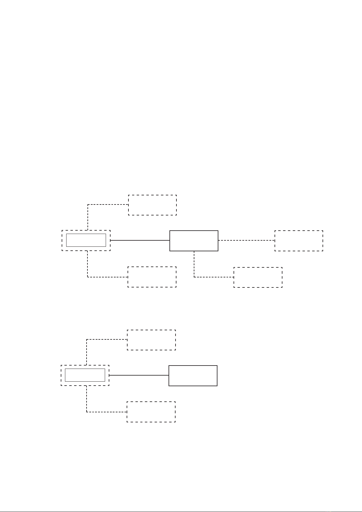
Therearetwobasicinstalledcongurationscoveredbythisguide.
Imager
Optional
Purge
Blower
Optional
Water
Cooling
Control Computer
Optional
Remote
Computer
Optional
Input/Output
Signals
Optional
Protection Jacket /
Back Cap / Air Purge
Control Computer Installation
PSU Installation
Imager
Optional
Purge
Blower
Optional
Water
Cooling
PSU
Optional
Protection Jacket /
Back Cap / Air Purge
Capable of providing 12 to 30V dc
Max 1% ripple
Voltage outputs isolated from local ground.

Page 2
NIR Thermal Imager Installation Guide
1.1 About the NIR thermal imager
The LAND NIR thermal imager is an accurate, focusable, NIR thermal imager
designed for use in conjunction with the LIPS NIR image processing software.
The thermal imager features include:
• Focusableopticalsystemwithrangefromunder600mmtoinnity
• A range of close-up lenses, enabling focus distances as low as 100mm
• Accurate measurement of target temperature
1.2 Unpacking the thermal imager
The package containing the camera will contain the following items:
• CD containing User Documentation.
• NIRCamera(ttedwithprotectioncaponthelens).
It is recommended that the front window protection cap is kept attached until
the camera is installed.
1.3 Nomenclature
The thermal imager detail label is on the rear face of the thermometer above
the LAND logo label. The instrument type nomenclature is explained below.
Make a note of your thermometers instrument type and Serial Number in the
space provided below.
Instrument type: NIR
Serial Number:
e.g. NIR 14 25
Denotes 1400°C
maximum temperature
Denotes 25mm focal length lens

Page 3
Installation Guide NIR Thermal Imager
2 Specifications
2.1 Configurations
Temperature Range Model Reference NIR
8 mm lens* 25 mm lens 50 mm lens 75 mm lens
600 to 1000 °C / 1112 to 1832 °F 10 - 08 10-25 10-50 10-75
800 to 1400 °C / 1472 to 2552 °F 14 - 08 14-25 4-50 14-75
1000 to 1800 °C / 1832 to 3272 °F 18 - 08 18-25 18-50 18-75
1400 to 3000 °C / 2552 to 5432 °F - 30-25 30-50 30-75
2.2 Optical Performance
Lens Type 8 mm lens 25 mm lens 50 mm lens 75 mm lens
Field of View (Horiz x Vert) 44° x 33° 14.4° x 10.8° 7.2° x 5.4° 4.8° x 3.6°
Focus Range 600 mm (2 ft) to innity (manual focus)
IFOV 1.2 mrad 0.40 mrad 0.20 mrad 0.13 mrad
Window Material Glass Glass Glass Glass
2.3 Close-up Lenses
Close-up Lens Ref: G1 G2 G3 G4 G5
Focal Range (mm) 100 to 123 120 to 160 150 to 215 200 to 340 250 to 495
Focal Range (inches) 4 to 4.85 4.7 to 6.3 5.9 to 8.5 7.8 to 13.4 9.8 to 19.5
2.4 Imager Performance
System Temperature Accuracy 0.5 % (K) up to 1600 °C / 2912 °F and 1% (K) above
Spectral Range 780 to 1100 nm
Detector Silicon focal plane array
Detector Array Format 656 x 494
Frame/Frequency 30 Hz (Gigabit Ethernet)
Operating Temperature Range 0 to 50 °C / 32 to 122 °F (non-condensing)
Storage Temperature Range -20 to 80 °C / -4 to 176 °F (non-condensing)
Operating Humidity 0 to 90 % non-condensing
Sealing IP65 / NEMA 4 (with Phoenix Ethernet connector)
Vibration 3 g between 10 and 300Hz
NIR Interfaces Separate sockets / lead for power and data connection
Power Range 12 to 30 V dc, 3 Watts
Data Out Digital data over Gigabit Ethernet (RJ-45)
Mountings Two ¼ in BSW mounting holes spaced 25 mm apart allow it be
mounted to a large range of accessories
Software Complete LIPS (Land Image Processing Software) package for
PC
Standard Accessories Power Supply, Cables, Software, Close-up Lenses
*8 mm lens requires hot target to ll minimum of 30% of scene to achieve stated accuracy
Page 4
NIR Thermal Imager Installation Guide
3 Installing the Thermal Imager
If the thermal imager is to be used in conjunction with a protection jacket and
air purge, refer to the installation guides provided with those accessories.
If the thermal imager is to be installed in a location where the ambient
temperatureiswithintherangesspeciedforthethermalimager,andno
air purging is required to keep the lens clean, the thermal imager can be
mounted using the two tapped holes on the mounting pad. Either hole can be
used for direct tripod mounting.
A swivel ball mounting (S4 - B) is available from Land infrared. This
mounting accessory enables you to easily adjust the thermal imager's line of
sight.
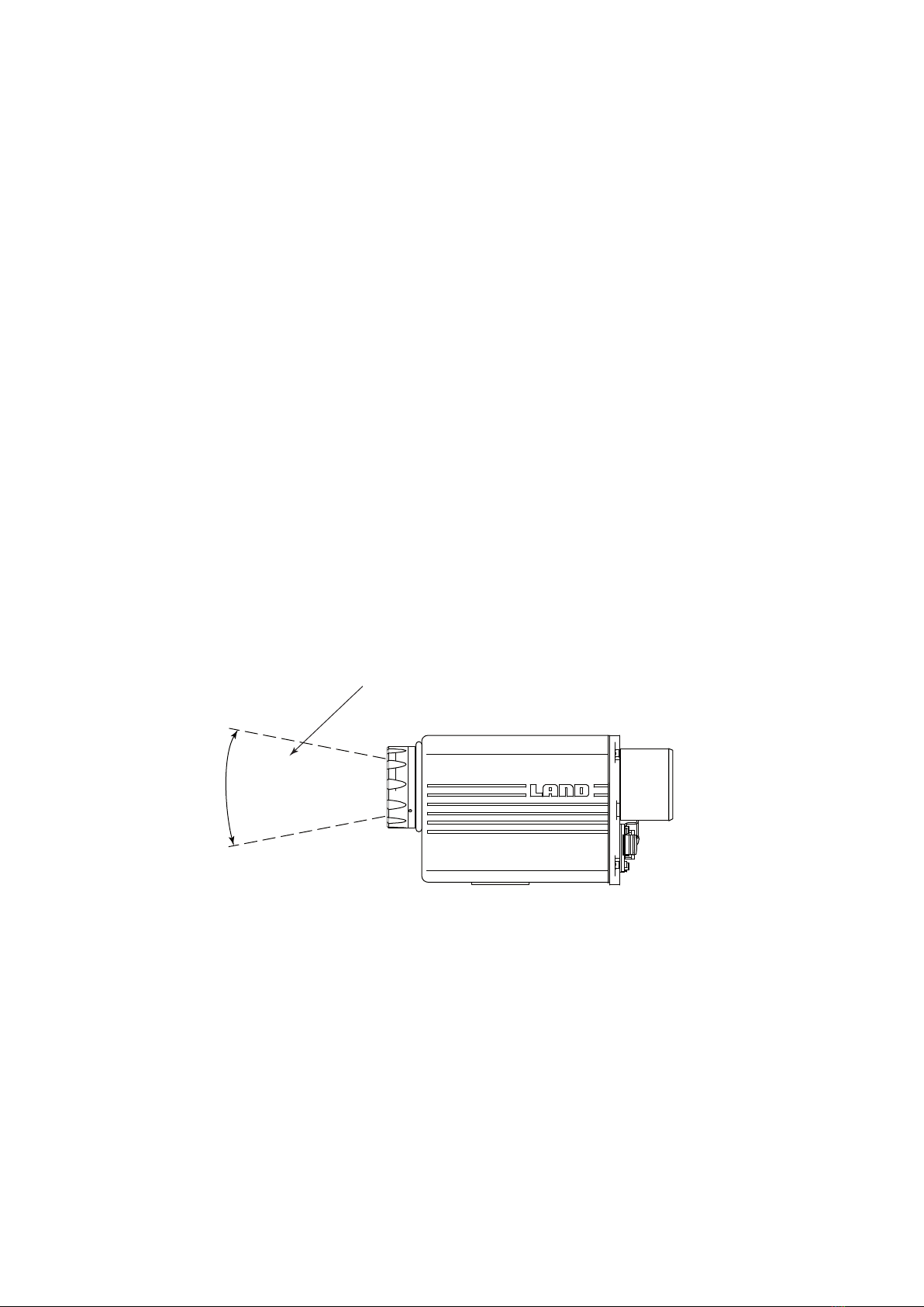
3.1 Fields of view
Fourhorizontaleldsofviewareavailable:
• 8mmfocallengthlensgivesanoverallFOVof44°
• 25mmfocallengthlensgivesanoverallFOVof14.4°
• 50mmfocallengthlensgivesanoverallFOVof7.2°
• 75mmfocallengthlensgivesanoverallFOVof4.8°
Fig.3Thermalimagereldofview
Ensure that the thermal imager has
an unobstructed view of the target area
Overall field
of view (vertical)
Inhaltsverzeichnis
Andere Ametek Wärmebildkamera Handbücher


