APsystems ECU-3 Bedienungsanleitung

Installation/User Manual
APsystems ECU-3
Energy Communication Unit (ECU)
Version 8.0 1/16
© All Rights Reserved APsystems.com

TABLE OF CONTENTS
INTRODUCTION 3
HARDWARE INSTALLATION 5
Preparation
Selecting an Installation Location for the ECU
Using Electrical Mounting Din Rail
Using Wall Mount 6
Cable Ports 7
Cable Connections
Internet Connection 8
Direct CAT5 Connection
Wireless Connection
Power Up ECU 9
ECU INITIALIZATION SEQUENCE 10
USING THE ECU MENU BUTTON 13
RESETTING THE ECU TO FACTORY DEFAULTS 15
TROUBLESHOOTING ECU OPERATION 16
LOCAL NETWORK INTERFACE 17
Connecting to the ECU via the LAN 18
Connecting Directly to the ECU
Using a Windows-based PC
Using an Apple Mac 19
Viewing the ECU’s Home Page 20
Managing Inverter UIDs 22
Initial Programming of the ECU with the Inverter UIDs
If Manually Entering the UIDs into the ECU 23
If Using a Scanning Gun to Enter the UIDs into the ECU
Adding Additional Inverter UIDs 25
Deleting an Existing Inverter UID
Changing the Date, Time Zone 25
Changing the ECU Language 27
Managing the Network Connection 28
Assigning a Static IP Address to the ECU
Managing The Wlan/Wifi Connection 30
To Change the ECU to WLAN Mode
REMOTE ECU MANAGEMENT 34
ECU Configuration 36
Setting the ECU Time Zone 37
Managing Inverter UIDs and Updating the Inverter UID List 38
TECHNICAL DATA 41
APsystems ECU-3 V7.0 Installation/User Manual

APsytems ECU-3 V8.0 Installation/User Manual 3 3
INTRODUCTION
The APsystems Communicator, our state-of-the-art Energy
Communication Unit (ECU), is the information gateway for our
microinverters. The unit collects module performance data from each
individual microinverter and transfers this information to an Internet
database in real time, requiring only a single data and power cable.
Through the APsystems Monitor software, the APsystems Communicator
gives you precise analysis of each microinverter and module in your
solar installation from any web-connected device. The APsystems
Communicator’s integrated http webserver offers the simplest and most
exible network integration of any data logger on the market. The user-
friendly browser-based interface lets you access your solar array in
seconds.
ECU functions as a gateway and monitors the microinverters that are
connected to the PV modules. Therefore, the communication between
inverters and ECU does not affect inverter performance, even if ECU fails
to communicate with the inverters. The ECU is NOT a revenue grade
metering device. Power production data collected by ECU is for reference
only, please check the power meter for the real power production of the
whole system.
Figure 1

APsytems ECU-3 V8.0 Installation/User Manual 4 4
Features
• Collects individual module and microinverter statistics
• Communicates in real time
• Requires no additional wiring
The APsystems Microinverter is used in utility-interactive grid-tied appli-
cations, and is made up of three key elements:
• APsystems Microinverter
• APsystems Energy Communication Unit (ECU)
• APsystems Energy Monitor and Analysis (EMA) web-based moni-
toring and analysis system
Figure 2
Diagram of a typical residential system
INTRODUCTION

APsytems ECU-3 V8.0 Installation/User Manual 5 5
HARDWARE INSTALLATION
PREPARATION
Make sure you have the following things taken care of before attempting
to install the ECU:
• A dedicated standard AC electrical outlet (located as close
electrically to the array as is possible).
• A broadband Internet connection is available for your use.
• A broadband router with either a CAT5 Ethernet, or wireless
router is available for your use.
• A laptop with a web browser (to view the APsystems EMA online
monitoring application).
• An ECU.
SELECTING AN INSTALLATION LOCATION FOR THE ECU
• A location that is as close electrically to the array as is possible –
preferably a dedicated outlet installed directly to the solar system
sub-panel or combiner box.
• The ECU is NOT rated for outdoor use, so if installing outdoors
near a junction box or breaker panel, making sure that you enclose
it in an appropriate weather proof NEMA electrical box.
Using Electrical Mounting Din Rail
1. Loosen the two (2) M3 mounting screws on the back of the ECU
and rotate the two (2) rail holders so that the holders are above the
ECU.
2. Attach the ECU to the mounting rail with machine screws.
Figure 3
Figure 4

APsytems ECU-3 V8.0 Installation/User Manual 6 6
HARDWARE INSTALLATION
Using Wall Mount
When mounting the ECU to a wall, make sure to select a cool, dry, indoor
location.
1. Depending on the wall surface you are mounting the ECU to, use
either two (2) #8 drywall screws or wall anchors, installed 130 mm
apart. The drywall screws and wall anchors are NOT included in
the ECU kit.
2. Align and slide the ECU onto the mounting screws.
Best Practice: Install and connect the ECU to the Internet (see below
instructions) while the rest of the array is being installed. Doing so allows
the ECU to automatically update its internal software while the rest of the
physical installation is underway. The ECU will then communicate with
the inverters when the installation is complete and the array is energized.
Figure 5
APsytems ECU-3 V8.0 Installation/User Manual 7 7
HARDWARE INSTALLATION
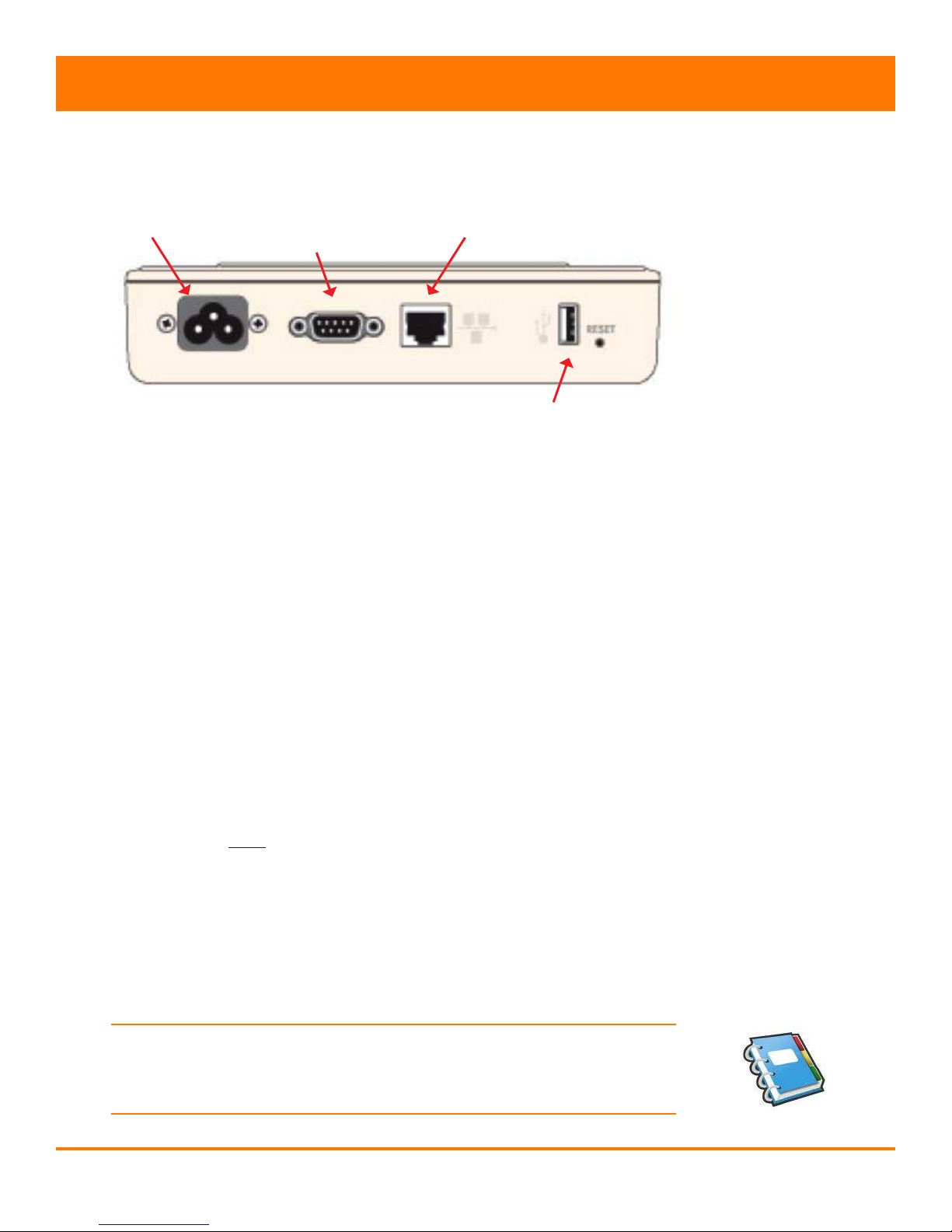
Cable Ports
Power Connection Port:
The power connection port is used to both supply the ECU with power, and
communicate with the inverters using the Power Line Communications
(PLC) protocol.
RS232 Serial Port:
The RS232 serial port can be used to connect the ECU to the Internet
using General Packet Radio Service (GPRS). GPRS is a cell technology
that is not available in all areas. Check with your cell phone service
provider for details regarding availability and service pricing.
Network Port (RJ45):
The network port (RJ45) is used to connect the ECU to your local network
via a CAT5 cable. This port can be used to connect directly to the network
router, or through a wi extender or PLC bridge.
USB Port:
The USB port can be used as a power source (5VDC) for a wi bridge if
necessary. It is NOT a two-way communication port, and is therefore
incompatible with external wi devices such as wi dongles or thumb
drives.
Figure 6
Power Connection Port Network Port
Network Port (RJ45)
RS232 Serial Port
CABLE CONNECTIONS
1. Connect the supplied power cable to the power connection port on
the bottom of the ECU.
NOTE: As noted in the previous section, the ECU communicates with the
inverters using the Power Line Communications (PLC) protocol through
the power connection port.

APsytems ECU-3 V8.0 Installation/User Manual 8 8
HARDWARE INSTALLATION
2. Connect the supplied CAT5 cable to the network port (RJ45) on the
bottom of the ECU.
INTERNET CONNECTION
There are two different approaches to connecting the ECU to the Internet:
• Direct CAT5 network connection to a broadband router.
• Wireless connection to a wireless broadband router.
NOTE: The ECU is NOT a wireless device and requires a wi extender or
bridge to make the connection to a wireless router.
NOTE: Make sure the ECU is connected to a router device – NOT a
modem or network switching device.
Direct CAT5 Connection
1. Make sure the CAT5 cable is connected to the network port on the
bottom of the ECU.
2. Connect the CAT5 cable into a spare port on the broadband router.
Wireless Connection
Using a wi extender:
1. Make sure the CAT5 cable is connected to the network port on the
bottom of the ECU.
2. Connect the CAT5 cable into the wi extender.
3. Join the wi extender to the site’s LAN.
Figure 7

APsytems ECU-3 V8.0 Installation/User Manual 9 9
HARDWARE INSTALLATION
Using a PLC bridge:
NOTE: A PLC bridge uses the power line to communicate and requires
both a “send” and “receive” unit.
1. Make sure the CAT5 cable is connected to the network port on the
bottom of the ECU.
2. Connect the CAT5 cable into the “send” unit of the PLC bridge.
3. Connect a CAT5 cable from the “receive” unit of the PLC bridge
into a spare port on the broadband router (refer to bridge users
manual for specic operating instructions).
POWER UP ECU
1. Make sure the power cable is correctly connected to the power
connection port on the bottom of the ECU.
2. Plug the power cable into a dedicated standard AC electrical outlet.
WARNING: Make sure to use a dedicated outlet for the ECU. Do NOT
plug any other devices into the same outlet as the ECU.
WARNING: Do NOT plug the ECU into a power strip, surge protector,
or uninterruptable power supply (UPS). The surge suppression and/
or ltering on these sorts of devices will substantially diminish PLC
performance.
Figure 8
Figure 9

APsytems ECU-3 V8.0 Installation/User Manual 10 10
ECU INITIALIZATION SEQUENCE
Once power is supplied to the ECU it automatically steps through a series
of initialization screens on its LED display.
ECU INITIALIZATION
1. Loading the software rmware.
2. Searching for the inverters.
A word about network communication protocols. The ECU needs to have
access to the router via an IP address. The ECU will only search for and
obtain a DHCP IP address during its powering up sequence.
For example, the LED screen on the front of the ECU displays an
IP address such as “192.168.2.101” if the connection to the router is
successful (the IP address will vary based on router supplier, so check
with the user manual for specics). If, however, the LED displays
“60.190.131.228”, the ECU-router connection has not been successful, in
which case you’ll need to check all of the cabling connections and reboot
the ECU by removing the power cable for a few seconds and reconnecting.
Figure 10
Figure 11
Figure 12
LED Display
Firmware Version
Router IP Address
Andere Handbücher für ECU-3
1
Inhaltsverzeichnis
Andere APsystems Steuereinheit Handbücher

Beliebte Steuereinheit Handbücher anderer Marken

Festo
Festo Compact Performance CP-FB6-E Stücklistenhandbuch

Elo TouchSystems
Elo TouchSystems DMS-SA19P-EXTME Bedienungsanleitung

JS Automation
JS Automation MPC3034A Bedienungsanleitung

JAUDT
JAUDT SW GII 6406 Series Kurzanleitung

Spektrum
Spektrum Air Module System Bedienungsanleitung

BOC Edwards
BOC Edwards Q Series Bedienungsanleitung


