Aqualisa SIERRA Bedienungsanleitung

SIERRA
INSTALLATION AND USER GUIDE
TM
CONCEALED/EXPOSED CONCENTRIC
VALVE WITH ADJUSTABLE KIT

2
GENERAL INFORMATION
This product complies with EN1111.
This product must be fitted in compliance with the UK Water Supply (Fittings)
Regulations. If in doubt please contact your local water authority.
TOOLS REQUIRED (TOOLS NOT SUPPLIED)
PTFE
We have taken great care to ensure that this product reaches you in
perfect condition. However should any parts be damaged or missing
please contact your point of purchase. This does not aect your statutory
rights. In addition if you require replacement parts please contact the
Aqualisa customer helpline on 01959 560010 for assistance.
CONTENTS
General Information 2
Tools Required (Tools not supplied) 2
Warranty 3
Before You Start 3
Installation Exposed 4
Installation Concealed 6
Fitting the Shower Kit 11
Cartridge Temperature Adjustment 14
Cleaning the Thermostatic Cartridge 15
User Instructions 17
General Cleaning 18
Trouble Shooting 18

3
WARRANTY
Aqualisa products are supplied complete with a 1 year guarantee that can
be upgraded by registering this product with Aqualisa.
For details see: www.aqualisa.co.uk/warranty
BEFORE YOU START
This shower should be installed by a competent person in compliance with
current Water Supply Regulations. For further details contact your Local
Water Authority.
a. Identify all components and check pack contents.
b. Turn o water supplies.
c. Suitable full bore isolation valves must be fitted to both supplies in
accordance with current Water Supply Regulations and our terms of
warranty. Valves must be accessible for warranty and servicing.
Before making any pipe connections all supplies MUST be
thoroughly flushed to remove any debris.
WATER SUPPLY REQUIREMENTS
Hot Water Maximum: 65˚C Cold Water Minimum: 5˚C
Recommended 60-65˚C Recommended 10-15˚C
Always maintain a 10˚C dierence between hot system temperature and
maximum hot setting of valve.
Operating Pressure Range: Min. 0.15 bar, Max. 5.0 bar
When water pressure is higher than 5 bar a pressure reducing valve (not
supplied) must be fitted before the mixer. A setting of 3 bar is recommended.
This valve is suitable for gravity stored, gravity boosted (pumped),
balanced high pressure and combination boiler systems.
For gravity and gravity pumped systems use 22mm supply pipes and
reduce to 15mm for connection to the shower valve.

4
Pump Installation: PUMPS MUST NOT BE FITTED DIRECTLY TO A
WATER MAIN. REFER TO PUMP MANUFACTURERS INSTALLATION
GUIDELINES. Ensure there is adequate flow through the pump to activate
the flow switches.
Combination boiler: MUST have a minimum rating of 24kW (80,000 Btu)
and be of the type fitted with a fully modulating gas valve.
N.B. Boiler performance may aect outlet temperature.
Operating pressures: Hot and cold supplies should be kept as even as
possible in order to ensure the maximum eciency of the mixer.
INSTALLATION
This product is suitable for concealed, falling and rising inlet supply pipes.
Exposed Shower Installation
1
Ensuring adequate provision to allow the water to discharge
safely to waste, turn on the supplies to flush the system through.
Attach pressure test equipment and pressure test the system in
accordance with Water Supply Regulations.
N.B. Turn o the water supply following system flushing.
2
Construct suitable 15mm inlet supplies at level 150mm centres.
Ensure the pipework protrudes a minimum of 100mm, measured
from the intended finished wall surface.
Valve body
Grub screws
Fixing nuts
Wall screws
Hexagonal
key
Wall plugs
Elbow cover plates
Mounting bracket
Filtered washers
Temperature
control handle
Elbows
On/o and
flow lever
On/o and flow
control handle
Copper olives
Inlet water supplies
As viewed from front on:
Left = HOT
Right = COLD
Pipe centres: 150± 1mm
Adjustable: 145 - 155mm
Pipe tails: 18mm
From finished surface

5
N.B. The inlet elbows are supplied at factory set 150mm centres. If
required, the inlet centres can be adjusted by winding the elbows
into the body to reduce the inlet centres, or out to increase the
inlet centres.
3
Once the wall surface has been finished, flush through the pipe
work prior to trimming the length of the pipes to 18mm, measured
from the finished wall surface.
N.B. We recommend using a rotary type cutter but if a hacksaw is
used, ensure the cut is straight and the pipe ends must be carefully
deburred and chamfered.
N.B. If plastic pipe is used, tube inserts must be fitted and must
not increase the diameter or extend the cut o length by more
than 2mm.
4
Place valve body against the wall
with elbows over the pipe tails
and mark around the base where
it sits on the wall. Remove valve
body, place mounting bracket
in centre of the outlined valve
position* and mark points for
fixing holes.
*Valve position
outline
5
Important - Use appropriate fixings suitable for wall type/
construction. Drill holes to suit required fixings (Use wall plugs
supplied if suitable).
6
Secure mounting bracket to the wall using the wall screws supplied
(if suitable).

6
7
Fit the elbow cover plates, fixing nuts and copper olives over
the pipe tails and insert the filtered washers into the elbows of
the valve.
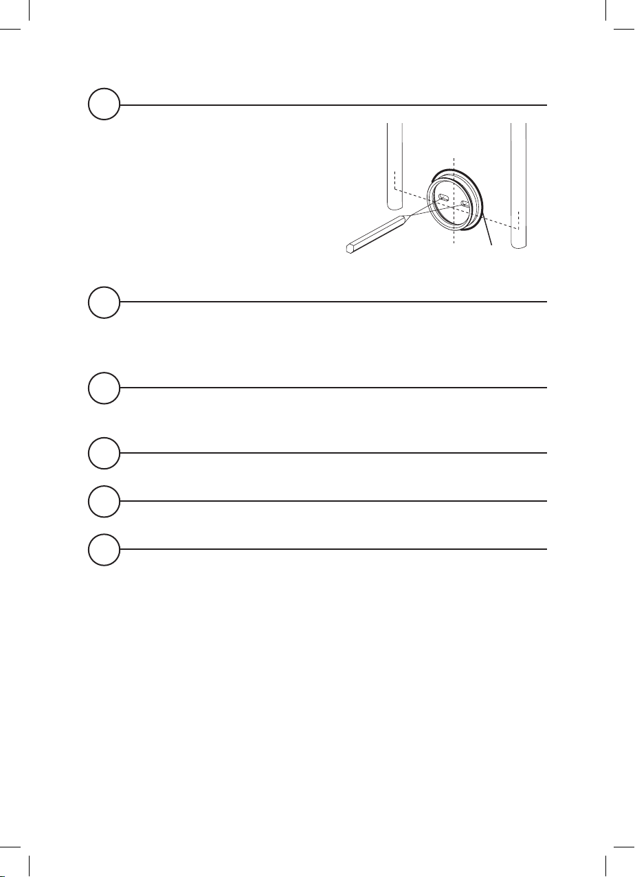
8
Making sure the outlet is at the bottom and that the elbows
align with the pipe tails, push the valve body onto the mounting
bracket, and secure with the two grub screws using the 2.5mm
hexagonal key (supplied).
Securely tighten the nuts of the elbows using a suitable spanner.
9
Fit the lever to the on/o and flow control handle.
10
Turn on water supplies and check for leaks.
Refer to page 13 for shower kit installation instructions.
Concealed Shower Installation
1
Pre-fitting checklist
Chase out a suitable recess in the wall to receive the valve and
pipework.
In most cases it will be necessary to first install a suitable sound
fixing / nogging in the cavity area to secure the valve.
A hole of Ø165mm is required to install the valve and gain access
to the inlet and outlet connectors.
N.B. The outlet connector can be repositioned to the top of
the shower valve as required to suit plumbing arrangements.
Simply swap with the blanking plug and ensure both are
securely re-tightened.
Construct suitable pipework.

7
IMPORTANT: Servicing and Maintenance access
To enable sucient access for ease of installation, servicing and
maintenance ensure:
Hot and cold feeds to the inlet elbows of the valve are from
falling or rising pipe work. (i.e. Elbow connections pointing
upwards or downwards).
The inlet elbows are wound in as far as possible to keep the pipe
centres to a minimum.
54 75
40
29
180
Wall plate diameter
Valve body
Temperature control handle
Grub screws
Blanking plug
Fixing nuts
Wall screws
Hexagonal key
Outlet connector
Mounting bracket
Wall plugs
Filtered washers
Elbows
Wall plate
Copper olives
On/o and flow control handle
On/O
and flow
lever
Wall plate diameter

8
2
Construct hot and cold supply pipes to the proposed siting.
Ensuring adequate provision to allow the water to discharge
safely to waste, turn on the supplies to flush the system through.
Attach pressure test equipment and pressure test the system in
accordance with Water Supply Regulations.
3
Turn o the water supply following system flushing.
4
Construct suitable 15mm inlet supplies at level centres and a 15mm
outlet supply pipe to the desired location for the wall outlet.
Inlet water supplies:
As viewed from front on: Left = HOT Right = COLD
Pipe centres: Adjustable: 145* - 155mm
Important: The inlet elbows are supplied at factory set 150mm
centres. *We strongly recommend keeping the inlet centres to a
minimum by winding the elbows into the body.
Pipework for the wall outlet needs to terminate in a suitable ½”
female connector (not supplied).
N.B. All pipework and connectors must be secured using
suitable fixings.
5
Trim pipework to the required length. Pipe insertion depth into the
elbow is 10-12mm (excluding nut and olive).
N.B. We recommend using a rotary type cutter but if a hacksaw is
used, ensure the cut is straight and the pipe ends must be carefully
deburred and chamfered.
N.B. If plastic pipe is used, tube inserts must be fitted and must not
increase the diameter or extend the cut o length by more than 2mm.
9
6
Place valve body into position
with elbows over the pipe tails
and mark around the base where
it sits on the mounting surface.
Remove valve body, place
mounting bracket in centre of the
outlined valve position* and mark
points for fixing holes.
*Valve position
outline
7
Important - Use suitable fixings for the mounting surface/
construction. Drill holes to suit required fixings (use wall plugs
supplied if suitable).
8
Secure bracket to the mounting surface using the wall screws
supplied (if suitable).
9
Fit the fixing nuts and copper olives over the pipe tails.
10
Insert the filtered washers into the elbows.
11
Making sure that the hot and cold inlet elbows align with correct
supplies, feed onto the pipes and push the valve body onto the
mounting bracket. Secure with the two grub screws using the
2.5mm hexagonal key (supplied).
Securely tighten the nuts of the elbows using a suitable spanner.

10
12
Using a suitable coupling connect pipework to the outlet of the
valve body.
N.B. The outlet connector can be repositioned to the top of
the shower valve as required to suit plumbing arrangements.
Simply swap with the blanking plug and ensure both are
securely re-tightened.
Outlet pipework needs to terminate in a suitable ½” female
connector (not supplied). Refer to Shower Kit installation
instructions page 11.
13
Turn on water supplies and check for leaks.
14
Install a cover panel (not supplied) or finish wall surface/tiles
leaving sucient access for future servicing and maintenance.
N.B. The wall plate can be used as a template for the access hole
size by placing it on the valve and drawing around the plate and
measuring in by 15mm to allow sucient surface area around the
hole to fit the wall plate.
15
When the finished wall surface is completed, fit the wall plate to
the shower valve and slide up to the wall surface (use a suitable
sealant as necessary). Screw the lever on to the on/o flow
control handle.
Andere Handbücher für SIERRA
2
Inhaltsverzeichnis
Andere Aqualisa Steuereinheit Handbücher


Beliebte Steuereinheit Handbücher anderer Marken

Festo
Festo Compact Performance CP-FB6-E Stücklistenhandbuch

Elo TouchSystems
Elo TouchSystems DMS-SA19P-EXTME Bedienungsanleitung

JS Automation
JS Automation MPC3034A Bedienungsanleitung

JAUDT
JAUDT SW GII 6406 Series Kurzanleitung

Spektrum
Spektrum Air Module System Bedienungsanleitung

BOC Edwards
BOC Edwards Q Series Bedienungsanleitung


