ASKOMA ASKOHEAT Bedienungsanleitung

ASKOHEAT-F+ Flange heater Ø 180mm
MV-012-6791.2 01.11.2021 www.askoma.com Page 1
Fitting instructions, user manual and service
Flange heater Ø 180mm
for drinking and heang water
AHFR-BI-plus-1.75 up to 5.8 kW
• AHFR-BI-plus-1.75
• AHFR-BI-plus-3.5
• AHFR-BI-plus-4.4
• AHFR-BI-plus-5.8
Index
General safety and assembly informaon Page 2
Operang instrucons Page 3
Assembly instrucons Page 4
User manual Page 6
Operang condions Page 7
Electrical diagram Page 8 / 9
Service Page 10
Malfuncon Page 10
Please keep in a safe place

ASKOHEAT-F+ Flange heater Ø 180mm
MV-012-6791.2 01.11.2021 www.askoma.com Page 2
Assembly information
The device must be installed horizontally, an installaon from above or below is not permiet for
safety reasons.
Make sure that the heang tubes are enrely covered by the liquid before placing into operaon.
The circulaon of the liquid shall not be inhibited.
Operang data, applicaon, dimensions and model of the ange heater are on the idencaon plate
and circuit diagram on the device, respecvely inside the housing cover, or can be found in the ng
instrucons / user manuals.
• Do not place the device into operaon unl aer having read the user manual.
• These devices may be used by children aged 8 or more and by persons with reduced physical, senso-
ry or mental capacity or those lacking in experience and/or knowledge if they are supervised or if
they have been instructed in safe operaon of the device and understood the resultant dangers.
Children may not play with the device. The device may not be cleaned or serviced by children unless
they are supervised.
General safety information
Installation, setting and removal must be
carried out only by qualified electri cians.

ASKOHEAT-F+ Flange heater Ø 180mm
MV-012-6791.2 01.11.2021 www.askoma.com Page 3
Operating instructions
Important information
If a heat exchanger is ed in the same tank, the controller must limit the temperature caused by the
heat exchanger to 85°C. This prevents the safety temperature limiter of the ange heater tripping.
Safety temp erature limiter
The safety temperature limiter may trip at temperatures lower than approx. –15°C (e. g. transportaon
or storage). If this happens, press the reset buon, see page 6 “user manual”.
The device may o nly be used to h eat water.
Corrosion protection
Please note: This heang element is applicable in stainless steel boiler as well as in black steel / black
steel enamelled boilers. Select the sengs via DIP switch according to the boiler type.
For an installaon of the heang element into black steel or black steel enamelled boilers, the red slide
switch (DIP switch) has to be le in posion “Schwarzstahlspeicher” (factory seng).
When installing the heang element into a stainless steel or chrome steel boiler, the slide switch
(DIP switch) has to be switched to posion “Edelstahlspeicher”.
Electri cal connection
The device is intended for xed connecon only and may be connected only to xed cables. Select a
cable cross-secon suitable for the power rang of the device. All poles of the device must be able to
be disconnected from the mains by means of an at least 3mm isolang distance. The PE wire must be
100mm longer than the other conductors.
In the event of the following the guarantee is vo id:
- Not complying with this paperwork „Fing instrucons, user manual, and service“
- Not complying with the storage heater manufacturer's ng instrucons
- Technical modicaons, repairs or tampering with the device (including exchanging the thermostat)
- Applicaons for which the device was not designed
- Incorrect operaon and maintenance
- Not complying with direcve VDI 2035
- Manipulaons on the operang soware
- Undocumented parameterizaons via the documented interfaces

ASKOHEAT-F+ Flange heater Ø 180mm
MV-012-6791.2 01.11.2021 www.askoma.com Page 4
Assembly instructions
1.
6.
3. 4.
5.
2.
Screw the flange heater including the seal onto the storage tank,
note the installation position , see „TO P“ sticker
Tighten screws by hand
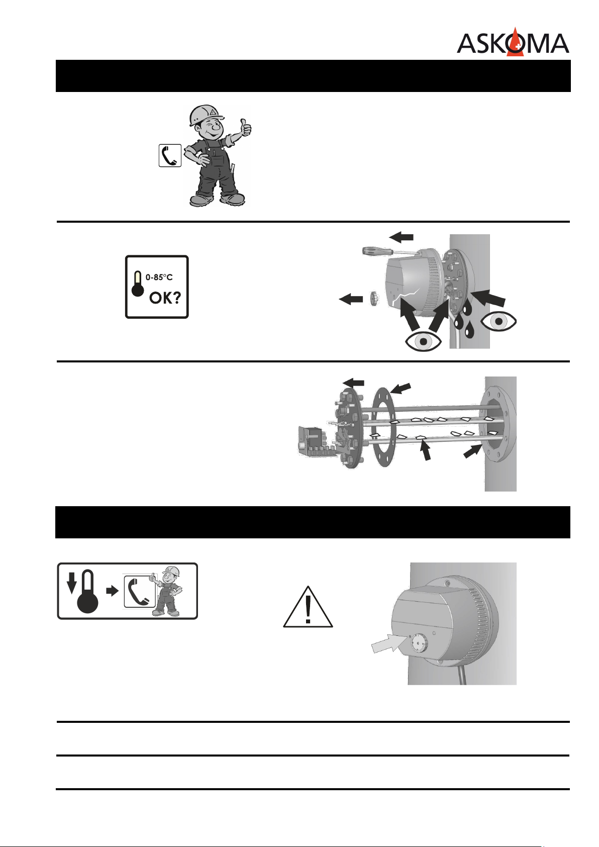
Carefully unscrew the housi ng cover
Clean the sealing surface of the flange
Tighten the screws with a torque wrench
Fill the tan k and check for leaks

ASKOHEAT-F+ Flange heater Ø 180mm
MV-012-6791.2 01.11.2021 www.askoma.com Page 5
Connect flange heater electrically
- Plug Z1—Connect the power supply to the heang element as follows:
Connecon 1: L1
Connecon 2: L2
Connecon 3: L3
Connecon N: N
Connecon PE: PE
- Plug Z2—Temperature sensor (oponal)
Connecon 1: Temperature sensor 1
Connecon 2: Temperature sensor 2
Connecon 3: Temperature sensor 3
Connecon 4: Temperature sensor 4
Connecon 5: GND
Connecon 6: Relay K4
- Plug Z3—Heat pump request / 0-10V analogue signal (oponal)
Connecon 1: GND
Connecon 2: Heat pump request
Connecon 3: Analogue input 0-10V
Connecon 4: RS485: A
Connecon 5: RS485: B
Connecon 6: RS485: GND
- Plug Z4— LAN connecon via data cable and RJ45 socket
Assembly instructions

ASKOHEAT-F+ Flange heater Ø 180mm
MV-012-6791.2 01.11.2021 www.askoma.com Page 6
User manual for the user and qualied installer
Device descr iption
The ASKOHEAT-F+ is switched in 7 steps via the digital Modbus interface or the analogue 0-10V input.
In addion, the maximum level up to 24 hours can be acvated via the „Emergency On“ buon (Pos. 2)
or the digital input „Heat pump request“.
The use of the interface is described in a separate document (Modbus protocl) and can be downloaded
from our homepage.
Temperature control
The maximum temperature can be connuously adjusted with the rotary knob (pos. 1). The range ex-
tends from „Out“ to approx. 85°C. For economic reasons, it should be set to approx. 65°C.
When the temperature is reached, the device switches o and on again automacally if necessary.
Safety temp eratur limiter
If the safety temperature limiter has tripped, you can reset it with a "00 screwdriver" through the
opening marked "Reset". This cannot be done unl the temperature has cooled down by approx. 10K.
Emergency operation „Emergency On“
The maximum heang output can be switched on immediately with the „Emergency On“ buon. To do
this, press the buon for at least 2 seconds. This may be necessary in the event of a fault or if addio-
nal heat is required. To switch o, press the buon again for at least 2 seconds. For safety reasons, the
ASKOHEAT-F+ automacally switches back to normal operaon aer 24 hours.
Safety: EN60335-1 / -2-21 / -2-73
EMC: EN55014-1 / -2
CEM: EN62233
IP Code: EN60529
Applicable
standards
Pos. 1 Temperature control
Pos. 2 Emergency On
Pos. 3 Reset buon
Pos. 4 Operang lights

ASKOHEAT-F+ Flange heater Ø 180mm
MV-012-6791.2 01.11.2021 www.askoma.com Page 7
Operating conditions
LED 1: STATUS
Blue Communicaon over ethernet (MODBUS TCP, RTU, webbrowser or HTTP-JSON
(e.g. Energy Manager) within last 5 seconds
Red—Flashing Error, for further informaon open the local webpages of ASKOHEAT+
White—Flashing Idenfy for 20 seconds or Emergency Mode toggles on or o / very fast ashing
at start and stop update
LED 2: CONNEC TION
Red Connecon to local network (LAN)
Green LAN (Ethernet) connected to a switch, hub or router
Yellow-ashing Data communicaon over LAN (Ethernet)
Blue-ashing ASKOHEAT+ is running without LAN connecon, e.g. using only analog input
LED 3: MODE
Yellow Heater relais are acve, but without current ow (switch-o by thermostat)
Green Heater is acve with current ow
Blue-ashing Emergency Mode is acve
White Idenfy for 20 seconds or Emergency Mode toggles on or o / very fast ashing
at start and stop update

ASKOHEAT-F+ Flange heater Ø 180mm
MV-012-6791.2 01.11.2021 www.askoma.com Page 8
Electrical diagram
WARNING! All power supply circuits must have been switched o before accessing
the connecon terminals.
Electrical and connecon diagram 1.75 kW
• AHFR-BI-plus-1.75

ASKOHEAT-F+ Flange heater Ø 180mm
MV-012-6791.2 01.11.2021 www.askoma.com Page 9
Electrical diagram
WARNING! All power supply circuits must have been switched o before accessing
the connecon terminals.
Electrical and connecon diagram 3.5 kW - 5.8 kW
• AHFR-BI-plus-3.5
• AHFR-BI-plus-4.4
• AHFR-BI-plus-5.8
ASKOHEAT-F+ Flange heater Ø 180mm
MV-012-6791.2 01.11.2021 www.askoma.com Page 10
Service
1.
2.
Malfunction
Reset
See user manual for the
qualied installer.
The device must be
cleaned (descaled) with
a suitable professional
descaling agent, e. g.
citric acid.
If the safety temperature
limiter trips, there is a fault
or error. A qualied expert
must inspect the system in
this case.
The version currently valid can be downloaded under "Downloads" from our homepage
2x / year
When the heater is used in hard water areas it must be
regularly descaled.
It is imperave that the local circumstances are paid aen-
on to.
The build up of scale in the heang element can lead to the
acvaon of the safety temperature limiter or thermal
overloading thereby destroying the heang elements.
In such cases the guarantee is not valid!
New
Needs cleaning
For technical data see the data sheet Subject to technical alteraons
Andere Handbücher für ASKOHEAT
1
Dieses Handbuch passt für folgende Modelle
4
Inhaltsverzeichnis
Andere ASKOMA Heizung Handbücher


Beliebte Heizung Handbücher anderer Marken


Empire Heating Systems
Empire Heating Systems WCC65 Bedienungsanleitung

Wetekom
Wetekom 92 86 43 Bedienungsanleitung

Desa
Desa SPC170-F Bedienungsanleitung

Watlow
Watlow Watrod Electric Tubular Heaters Bedienungsanleitung

Haverland
Haverland ECO-DRY GPS Series Stücklistenhandbuch

Stelpro
Stelpro ASILVC2060 Series Bedienungsanleitung