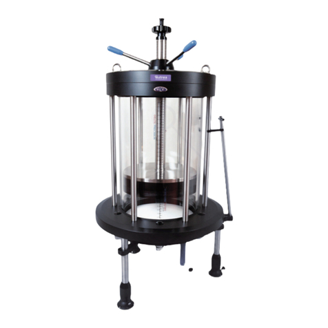
Astrea Evolve Bedienungsanleitung

Evolve®350mm Column
Instructions for Replacing the Wetted
Flowpath using the Column Refresh Kit

Evolve®350mm Column: Instructions for Replacing the Wetted Flowpath using the Column Refresh Kit
2
Table of Contents
Replacing the Wetted Flowpath ........................................................................................ 3
General Guidelines ........................................................................................................ 4
STAGE 1 –Refresh the Adjuster Assembly ............................................................................ 6
Step 1-Disassembly of Adjuster Assembly............................................................................. 6
Step 2-Reassembly and Refresh the Adjuster Assembly ............................................................ 8
STAGE 2 –Refresh the Tube Unit Assembly..........................................................................10
Step 1-Disassembly of the Tube unit ................................................................................. 10
Step 2-Reassembly and Refresh the Tube unit ...................................................................... 12
STAGE 3 –Refresh the Fixed End Assembly..........................................................................13
Step 1-Disassembly of the Fixed End Assembly ..................................................................... 13
Step 2-Reassembly and Refresh of the Fixed Assembly ............................................................ 14
STAGE 4 - Column Reassembly and Preparation For Use..........................................................15
Step 1 –Assemble Tube Unit onto the Column base and Bottom flowcell. ..................................... 16
Preparing for Column Use ...............................................................................................18
Step 1 - Hydrostatic Leak Test ........................................................................................ 18
Step 2 - Levelling the 350mm Columns .............................................................................. 18

Evolve®350mm Column: Instructions for Replacing the Wetted Flowpath using the Column Refresh Kit
3
Replacing the Wetted Flowpath
This manual describes the procedures necessary to replace the wetted flowpath components in the Evolve®350 column
using the Column Refresh Kit AA35CRK3.
Description
QTY
Flow Tube Adaptor 10mm Bore
1
Adjuster Flow Tube with seals 10mm Bore
1
Flow Tube Seal,10mm Bore
3
Bed Support retaining ring
1
Bed support retaining bolt
2
Adjuster Seal, 350mm Column
1
Adjuster bed support
1
Fixed bed support
1
Fixed bed support seal /Fixed Tube Seal
3
Fixed cell seal
1
Pipespool Elbow
1
Flow Tube Seal, Ladish 10mm Bore
3
Click Clamp
3
Blanking caps
2
Adjuster Cell 350 assembly including flowtube
adaptor, bolts and inserts and gasket
1
Fixed cell assembly including flowtube adaptor,
bolts, inserts and gasket
1
Fixed Flange
1
Locking Flowcell Nut
1
Tube, 350 X 530
1
Buffer Ring, 350
2
Scale Label, 350
1
Serial Number Label
1
Rating plate
1
Alignment Indicators
2
Evolve Label
1
Fitting Instructions
1
Figure 1 List of Refresh Kit components and Column
schematic. Parts shown in RED are the wetted
flowpath components.

Evolve®350mm Column: Instructions for Replacing the Wetted Flowpath using the Column Refresh Kit
4
General Guidelines
There are four main stages to refreshing the column by replacing the wetted flowpath. The first three stages are based
on the disassembly and reassembling each column sub assembly with new components before the final stage of
rebuilding and testing the complete column.
STAGE 1 –Refresh the Adjuster Assembly of the Evolve®350 Process Column
STAGE 2 –Refresh the Tube Assembly of the Evolve®350 Process Column
STAGE 3 –Refresh the Fixed Assembly of the Evolve®4350 Process Column
STAGE 4 –Rebuild and Test the Evolve®350 Process Column
To disassemble and assemble the columns follow the instructions below. After reassembling the column ensure that the
column does not leak by performing a hydrostatic leakage test.
NOTES: When assembling/dissembling attention should be paid to:-
1. Always use the correct size tools. A comprehensive tool kit was provided with the original column. See Table
below.
2. Ideally components should be at approximately room temperature. If not, take particular care as thermal
expansion or contraction may make components fit more tightly and thus more difficult to disassemble.
3. Dismantled assemblies should be rested on a clean, dry surface.
4. Pay particular care not to damage the edge of the flowcells.
5. When unpacking columns be careful not to scratch the inside of the column tubes.
6. Be careful not to damage stainless steel surfaces by bumping, knocking or scratching.
7. Do not over-tighten components and use correct torque settings as given in this guide.
8. Good engineering practices should always be followed and operations carried out in an approved and safe manner.
9. The components of the Evolve®350 column are heavy and large. Mechanical handling equipment or manual
handling aids should be utilised to safely lift or move the Column or its subassemblies. Provision is made for the use
of a hoist as eye bolts are fitted or supplied. It is essential that ‘good practice’ is adopted regarding the use of
appropriate slings and associated equipment. See original column manual for guidance.
10. All these operations should be performed by two people.
CAUTION!
THESE PROCEDURES MUST BE PERFORMED USING AN OVERHEAD HOIST

Evolve®350mm Column: Instructions for Replacing the Wetted Flowpath using the Column Refresh Kit
5
The following tool kit was provided with the original column.
Tool
Where used
Allen Key Set
Various locations
Torque Wrench and 14mm Socket
Tie Bar fixing Bolts
Spanner 17mm/13mm AF
Flowtube adaptor, Adjuster Flowtube, Column Feet
Spanner 19mm/24mm
Flanges bolts Adjuster, Fixed and locking flowcell nut
Spirit Level
Used to level the column
S/Driver with Wide Blade
Removal of bed support retaining ring
Eye Bolt
Additional eye bolts to fit to tube unit during
maintenance procedures
Alignment indicators are attached to the top flange, tube flanges, bottom flowcell and column base. These assist with
reassembly of the column and ensure correct orientation of the column components.
Figure 2 Photograph of Evolve®350 showing alignment indicators.
Alignment Indicators

Evolve®350mm Column: Instructions for Replacing the Wetted Flowpath using the Column Refresh Kit
6
STAGE 1 –Refresh the Adjuster Assembly
Step 1-Disassembly of Adjuster Assembly.
1. Detach any pipework from the top sanitary clamp adapter.
2. Remove flange fixing bolts from the top column tube flange. Retain bolts, nuts
and washers.
3. Check that adjuster seal is released by turning the seal actuation nut counter
clockwise.
4. If necessary, remove the handles from the seal actuation nut if they interfere
with the hoist slings.
5. Using a hoist lift adjuster unit out of tube unit.
6. Move the adjuster along the hoist rail or move the remaining column unit so
access to the lifted adjuster unit is possible.
7. Place the adjuster assembly so that the flowcell face is on the floor with the
hoist still attached.
Identify the parts as shown in the schematic and photograph below.
CAUTION!
Adjuster units are very heavy. Lifting should only be done using appropriate lifting aids.
Figure 3 Photograph of
Evolve®350 Adjuster unit
removal from column tube
Figure 4 Adjuster Assembly Evolve®350 column

Evolve®350mm Column: Instructions for Replacing the Wetted Flowpath using the Column Refresh Kit
7
a) b) c) d)
Figure 5 Disassembly stages of the Adjuster Assembly
8. Remove sanitary clamp adaptor using the 17mm spanner and flowtube seal.
9. Remove the seal actuation nut and spacer (see a) of Figure 5).
10. Slowly, using the hoist, lift the adjuster flange. This will cause the flowtube, seal setting tube and flowcell to slide
out of the threaded rod (see b) Figure 5).
11. Stand the flowcell on a flat surface (see c) Figure 5.
12. Using “flats” on undo the seal setting tube and slide it upwards and retain.
13. Using correct spanner to remove the flowtube and discard.
14. Discard the adjuster bed support, flowcell, bed support retaining ring and bed support retaining bolt (see d)
Figure 5).
15. Lower the remaining components of adjuster assembly onto a flat surface.
16. Disconnect the hoist.
17. Refer to the table below and ensure the correct components are retained and discarded.
ADJUSTER ASSEMBLY
Wetted Flowpath components
DISCARDED
Non-wetted components
RETAINED
Sanitary Clamp Adaptor
Seal Actuation Nut
Flowtube seals x2
Spacer
Flowtube
Stainless steel Seal Adjust tube
Adjuster bed support
Threaded central height adjust rod
Adjuster Flowcell assembly, inc flowcell inlet, flowcell
locking nut and gasket seal
Height adjust handle assembly
Adjuster seal
Adjuster Flange
Bed support retaining ring
Seal setting ring
Bed support retaining bolt
Backing Plate

Evolve®350mm Column: Instructions for Replacing the Wetted Flowpath using the Column Refresh Kit
8
Step 2-Reassembly and Refresh the Adjuster Assembly.
The adjuster flowcell is supplied as an assembled unit which simplifies adjuster assembly protocols. Refer to
photographs below to provide visual guidance through the procedure.
a)
Figure 6 Assembly stages of the Adjuster Assembly
1. Place the adjuster flowcell on a flat surface (see a) Figure 6) and check the flowcell locking nut is located against
the flowcell (see b) Figure 6).
2. Locate the flowtube seal and fit the flowtube. Use the correctly sized spanner to tighten (see a) Figure 7).
a) b) c) d)
Figure 7 Assembly stages of the Adjuster Assembly –Connection to back of Adjuster Flowcell
3. Slide the stainless steel central seal setting tube over the flow tube and connect to the flowcell inlet ensure that
the tube is fully engaged and no manual rotation can be achieved (see b) Figure 7).
4. Move the flowcell locking nut upwards so it contacts the end of the seal setting tube (see c) Figure 7).
5. Tighten the seal setting tube against the locking nut (see d) Figure 7).
6. Fit the adjuster seal around the perimeter of the top flowcell.
7. Ensure eye bolts are fitted to the adjuster flange.
8. Using appropriate lifting slings attach the hoist to the adjuster assembly and lift the unit high enough to allow the
flowcell assembly to be fitted.
b)
CAUTION!
Do not over tighten as this may lead to failure of the component

Evolve®350mm Column: Instructions for Replacing the Wetted Flowpath using the Column Refresh Kit
9
a)
Figure 8 Reassembly of Adjuster Assembly
9. Move the adjuster assembly over the flowcell and lower so the flowcell assembly slides into the threaded height
adjust rod/seal setting ring assembly (see a) Figure 8) and ensure the adjuster seal is not trapped beneath the seal
setting ring (see b) Figure 8).
10. Locate the spacer and fit the seal actuation nut (see c) Figure 8).
11. Locate the flowtube seal and fit the sanitary clamp adapter.
12. The refresh of the adjuster assembly is now complete. Ensure the unit is firmly seated on the floor and detach the
hoist.
b)
c)
CAUTION!
Do not over tighten as this may lead to failure of the component

Evolve®350mm Column: Instructions for Replacing the Wetted Flowpath using the Column Refresh Kit
10
STAGE 2 –Refresh the Tube Unit
Assembly
Step 1-Disassembly of the Tube unit.
1. Attach the spare set of eye bolts provided with the original column, to the top tube flange.
2. Using appropriate lifting slings or equipment attach the hoist to the eye bolts.
3. Identify the components on the schematic shown in Figure 9.
Figure 9 Column Tube unit
TUBE UNIT ASSEMBLY
Wetted Flowpath components
DISCARDED
Non-wetted components
RETAINED
Tube (complete with scale label, Id labels)
Top column flange
Buffer seals
Tie bars and bolts
Bottom column flange
Bottom flange bolts, washers and nuts
4. Using the correct spanners, remove and retain the column tube bottom flange bolts, washers and bolts.
5. Lift up the column tube unit and when suspended loosen the tie bar fixing bolts that are located in the bottom
column flange.
6. Place the tube unit on a flat surface.
Andere Handbücher für Evolve
1
Inhaltsverzeichnis
Andere Astrea Industrieanlagen Handbücher