
ATSC AT2016 Bedienungsanleitung

AT2016
ON
OFF
CHANNEL
Please read thisUser Manual carefullyto ensure properuse of thisproduct and
keep this manualfor future reference.
USER MANUAL
ATSC CONVERTER BOX
AT2016

Table of Contents
Important Safety Instructions....................................................................1
1. Introduction.........................................................................................4
1.1 Remotecontrol ..................................................................................5
1.1.1 Installingthe batteries......................................................................6
1.1.2 Usingthe remote control ..................................................................6
1.2 Front Panel and Rear Panel Illustration ............................................... 7
1.2.1 FrontPanel.....................................................................................7
1.2.2 RearPanel .....................................................................................7
1.3 Connecting yourAtsc Converter Box.................................................... 8
1.3.1 Connecting Antennas.......................................................................8
1.3.2 Connecting to aTV Set.....................................................................9
1.3.3 Connecting toan Audio System....................................................... 10
2.On-Screen Menus................................................................................11
2.1 Auto Program....................................................................................11
2.2 Manual Channel Set..........................................................................12
2.3 Password ........................................................................................ 12
2.4 Parental control................................................................................ 12
2.5 Advanced Closed Caption.................................................................. 13
2.6 Language......................................................................................... 14
2.7 Auto Power Down Timer.................................................................... 14
2.8 Smart Antenna.................................................................................. 14
3. Troubleshooting................................................................................ 15
4. Specifications ................................................................................... 16
5. Glossary............................................................................................ 17
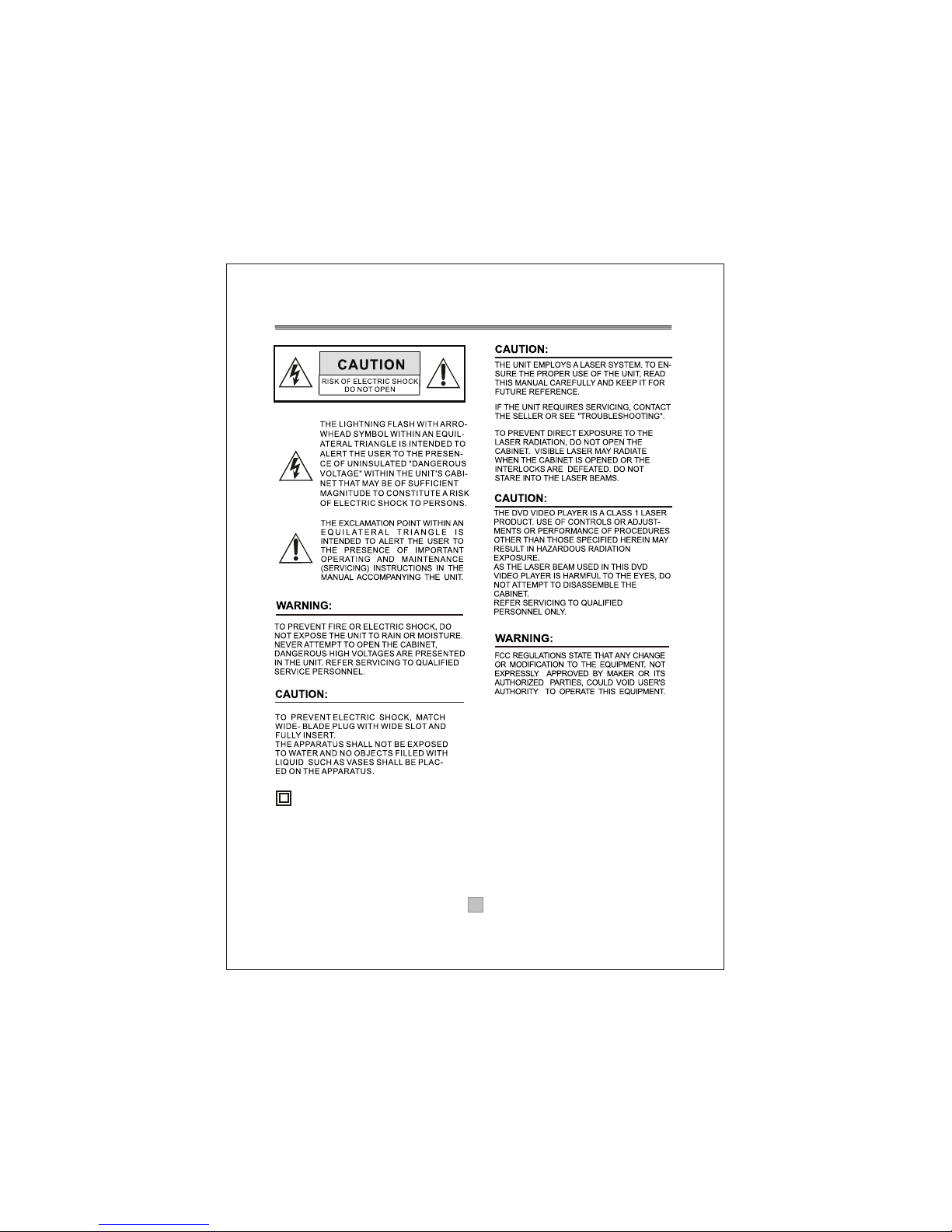
Important Safety Instructions
This symbol indicates that this product incorporates
double insulation between hazardous mains voltage
and user accessible parts. When servicing use only
identical replacement parts.
WARNING: To reduce the risk of fire or electric shock,
do not expose this apparatus to rain or cords.
1. The apparatus shall not be exposed to dripping
or Splashing and that no objects filled with liquids,
such as Vases, shall be placed the apparatus.
2. The mains plug is used as the disconnect device,
the disconnect device shall remain readily operable.
3. To be completely disconnect the power input,
the mains plug of apparatus shall be disconnected
from the mains.
4. The mains plug of apparatus should not be
obstructed or should be easily accessed during
intended use.
5. The battery (battery or batteries or battery pack)
shall not be exposed to excessive heat such as
sunshine, fire or the like.
1

1. Read these Instructions.
2. Keep these Instructions.
3. Heed all Warnings.
4. Follow all instructions.
5. Do not use this apparatus near water.
6.
7. Do not block any of the ventilation openings.Install in accordancewith the
manufacturers instructions.
8. Do not install near any heat sources suchas radiators, heatregisters, stoves,
or other apparatus(including amplifiers) that produce heat.
9. Do not defeat the safety purpose of thepolarized or grounding- type plug.
A polarizedplug has two blades with one wider than the other. A groundingtype
plug has twoblades and a third grounding prong. The wide blade or the third
prong are provided for your safety. When theprovided plug doesnot fit into your
outlet, consult anelectrician for replacement of the obsolete outlet.
10. Protect thepower cord from being walked on or pinched particularly at plugs,
convenience receptacles, andthe point where they exit from the apparatus.
11. Onlyuse attachments/accessories specifiedby the manufacturer.
12. Use onlywith a cart, stand, tripod, bracket, or table specified by the
manufacturer, orsold with the apparatus. When a cart is used, use caution when
moving the cart/apparatuscombination to avoid injury from tip-over.
13. Unplug thisapparatus during lightning storms or when unused for long
periods of time.
14. Refer allservicing to qualified service personnel. Servicing is required when
the apparatus hasbeen damaged in any way,such as power-supply cord or plug
is damaged, liquidhas been spilled or objects have fallen into the apparatus,
the apparatus hasbeen exposed to rain or moisture , does not operate normally,
or has beendropped.
Clean only with dry cloth.
Portable Cart Warning
2

Note:
1. Important safetyinstructions shall beprovide will each appliance.
These safety instructionsmay be inthe form of a separate booklet, separate
sheet, or partof the instructionmanual.
2. If includedin the instructionmanual, the safety instructions shall be located
before any operatinginstructions. 3. Theseinstructions shall beentitled
IMPORTANTSAFETY INSTRUCTIONS .
4. The safetyinstructions shall include,as applicable tothe particular apparatus,
the information andwarnings listed before.The wording iscapable of being
supplements, although notreplaced, by drawingor cartoons.
5. The symbolshall be shownadjacent to thetext of ImportantSafety Instructions
Warning: Changes or modifications to this unit not expressly approved bythe
,
party responsible forcompliance could voidthe users authority to operate the
equipment.
NOTE: This equipmenthas been testedand found tocomply with thelimits for a
Class B digitaldevice, pursuant toPart 15 of the FCC Rules. These limits are
designed to providereasonable protection againstharmful interference in a
residential installation. Thisequipment generates, uses,and can radiateradio
frequency energy and, if not installed and used in accordance with the
instructions, may causeharmful interference toradio communications. However,
there is noguarantee that interferencewill not occur in a particular installation.
If this equipmentdoes cause harmfulinterference to radio or television reception,
which can bedetermined by turning the equipment offand on, theuser is
encouraged to tryto correct theinterference by one or more of the following
measures:
- Reorient or relocate the receiving antenna,
- Increase the separation between the equipment and receiver.
- Connect the equipment into an outlet on acircuit different fromthat to
which the receiveris connected.
- Consult the dealer or an experienced radio TV technician for help.
3

Thank you forpurchasing this productwhich has been designed and manufactured
to give youmany years of service.
About This UserGuide
This user guidecontains all the information you need to know about how to setup
and watch availabledigital TV channelsusing thisATSC ConverterBox.
What's ATSC?
Advanced Television system committee, an international organization
establishing broadcasting standardsfor digital (includinghigh-defimtion
and data broadcasting)television.
What's Digital Television?
Digital television (DTV)is a newway of transmitting high quality video and audio
to your TVset. Using DTV, broadcasters can transmit high definition TV (HDTV)
images, Dolby digitalsurround audio, andnew services such as multiplexing
(transmitting more thanone program onthe same TVchannel) and datacasting
(providing electronic programguides and interactivetelevision). Several of these
services can becombined into a single digital broadcast.
How to ViewDigital Television?
DTV is broadcastfrom transmitters andreceived via a rooftop aerial. It works like
traditional TV, but becausethe signals areDigital you needan AtscConverter Box
to convert them.There are threeways to watchDTV: an external DTV Atsc
Converter Box receiverto a DTV-ready television oran integrated digital TV with
a built-in digitaltelevision tuner orpersonal computer (PC) tuner cards and
computer monitors.An AtscConverter Box receiver is the most popular case.
Look out for this symbol. Itindicates useful and important tips
4
Introduction

AT2016
1.1 Remote Control
5
Remote Key Function:
1. MUTE: Press to mute orunmute the audio output.
2. GUIDE: Press to display theon-screen Electronic Program
Guide (EPG).
3. CH+: Press to change thechannels in non-menu state.
4. CH-: Press to change thechannels in non-menu state.
5. INFO: Press to display informationabout the channel being
viewed.
6. EXIT:Press to completely exitfrom the on-screen menus.
7. OK: While using the on-screenmenus, press ENTER to
activate (or change) aparticular item.
8. : Press to move aroundthe menu screens
9. PRE-CH: Press to return tothe previous channel youviewed.
10. - : Press to input dashto select a channel,for example 14-1.
11. CAPTION:When a digital signal is received, Service1,
Service2,... or Service6 canbe selected. When ananalog
signal is received, CC1,CC2, CC3, or CC4can be selected.
12. AUDIO: Press to select theavailable multi-tracks.
(Depending on the particularbroadcast, one or more
foreign language translations mightbe available.)
13. STANDBY: Press to switch the Atsc Converter Boxto on
and off.
14. VOL+: Press to increase theoutput volume level.
15. VOL-: Press to decrease theoutput volume level.
16. : Press to move aroundthe menu screens
17. MENU: Press to display themain menu or toswitch
back to the previousmenu screen that wasdisplayed.
18. : Press to move aroundthe menu screens
19. : Press to move aroundthe menu screens
20. NUMBER KEYS Press to directly tuneto a particular
channel or input digitsin menus.
21. ASPECT:Press to change thescreen format (Normal/
Zoom/Wide/Cinema) according to thescreen aspect ratio
and the input signalformat.
22. SIGNAL: Press to show thesignal strength.

6
1.1.1 Installing theBatteries
Remove the battery cover from the remote control and put 2xAAA size batteries
inside the compartment.
The diagram inside the battery compartment shows the correct way to install the
batteries.
OPEN
OPEN
1.Open the cover 2.Install batteries 3.Close the cover
1.1.2 Using theRemote Control
Touse the remote control, point it towards the front of the digital
The remote controlhas a range of up to 7 metres from the
at an angleof up to 60 degrees.
The remote controlwill not operate if its path is blocked.
Atsc Converter
Box. AtscConverter
Box
Sunlight or very bright light will decrease the sensitivity of the remote
control.

CH 4
100-240V~
50/60Hz
R
LVIDEO
SERVICE
ATSC NTSC
SMART ANT. I/F
Serial No.:
RF OUTRF IN
Audio Out
Video Out
MODEL: AT2016
ATSC CONVERTER BOX
POWER SUPPLY: 100-240V~ 50/60Hz
MAX POWER CONSUMPTION: 8 WATTS
CH 3
This device complies with Part 15 of
the FCC Rules. Operation is subject
to the following two conditions:
(1) this device may not cause harmful
interference, and (2) this device must
accept any interference received,
including interference that may cause
undesired operation.
CONFORMS TOU L
STD.60065
CERTIFIEDTO CSA
STD.C22.2 No. 60065
AT2016
ON
OFF
CHANNEL
7
1.2 Front Paneland Rear Panel Illustration
1.2.1 Front Panel
1
2 RF OUT: This socket willtransmit the NTSC CH3/4RF signal to your TV ANTin socket.
3 CH3/4 SWITCH: Select NTSC channel (Channel3:61.25MHz,Channel4:67.25MHz).
4
5
6
7 SERVIC
8 MAIN POWER:Connect to mainpower supply usingthe power cord.
RF IN :
AUDIO L/R:
:This RS-232 PORTfor softwareupgrade by manufacturer only and not for user.
Connect theAIR antenna orCATV cablehere.(if the cable provider is passing
through 8VSB signal.)
SMART ANT I/F:Connect to an external smart antenna.
Connect these terminals tothe analog audio inputsof a TVset (i.e., to a
TV that hasjacks for L/R inputs). Or connect these terminals to the L/R inputs of a
separate audio component.
Video output: Connect this jack to the VideoInput jack onyour TV usingan Audio/Video
cable.This output port supportsthe only SD output..
1 POWER BUTTON: Used to turn onor off of the main power ofthe unit.
2 REMOTE CONTROLSENSOR: Used to receivethe signal from the remote control.
3 STANDBY INDICATOR: Used to visuallyshow power stateof the ,
the red LEDwill be light if the entered standby mode.
4.CHANNEL UP/DOWN: Used to change the channels in non-menu state.
Atsc Converter Box
Atsc Converter Box
1 2 3456
1.2.2 Rear Panel
7 8
1.3 Connecting TheAtsc Converter Box
The following diagramsare of typical configurations only, and may differslightly
to your existingexternal equipment. If you are unsure how to connect to your
Atsc Converter Box, always consultyour manufacturer's usermanual supplied
with your equipment.
1.3.1 Connecting Antennas
This section tellshow to connect an indoor or outdoor antenna to your Atsc
Converter Box.You may need a 75~ adaptor or a combiner.
NOTES:
A. If yourantenna has separateleads for VHF/UHF signals, you will need
to purchase acombiner to combine it before connect to the receiver.
B.The AtscConverter Box canreceive DTV signals in the event that a local cable
provider is passing8VSB through ontheir system. (8VSB is the RF modulation
format utilized bythe DTV(ATSC)digital television standardto transmit digital
bits over theairwaves to thehome consumer.)
C. When ReceivingDigital Cable Signal : If your cable service signal does not
comply with theATSCrequirement, this productmay not operateproperly.
8
Inhaltsverzeichnis


