
Audio Authority Car Audio System Bedienungsanleitung

å
Demonstration Network
Car Audio
System Installation Manual
The Access™ Demonstration Network is protected by U.S. Patent numbers 5,4 ,631 and 5,646,60 with
foreign patents pending.
Audio Authority, and the double-A symbol are registered trademarks of Audio Authority Corporation.
Access, AccessEZ, AccessPC, SilenTouch, AutoDamping, AutoLimiting, AutoCal, and TheftAlert are
trademarks of Audio Authority Corporation. The software imbedded within the Access™ System is not sold,
but rather licensed for this product specific use. The original purchaser is licensed to use this software in this
product and this application only. Under this license, the software may not be reproduced, copied,
disassembled, distributed by any means, licensed, rented, sold, or in any way revealed to or used by a third
party.
752-267
9/00
048 Mercer Road, Lexington, Kentucky 40511-1071
Phone: 859- 33-4599 • Fax: 859- 33-4510
Customer Toll-Free USA & Canada: 800-3 -8346
Website: http://www.audioauthority.com

2

3
PREPARATION ................................................................................... 15
ADDRESSING .................................................................................... 15
INSTALL THE SYSTEM HARDWARE ................................................ 19
INSTALL THE BUS CABLES .............................................................. 20
CHECK YOUR WORK TO THIS POINT .............................................. 26
INSTALLING A CONTROL PANEL .................................................... 28
CONNECT ACCESSORIES TO THE 980 SYSTEM MODULE .......... 31
TESTING NETWORK FUNCTION ..................................................... 32
COMPONENT HOOKUP .................................................................... 34
DEMONSTRATION FEATURES ......................................................... 38
Contents
CHOOSING THE CORRECT SWITCHING MODULES ..................... 12
HEAD UNITS ...................................................................................... 12
PROCESSORS, EQUALIZERS AND BYPASS .................................. 12
AMPLIFIERS AND AMP SHARING.................................................... 13
AMPLIFIER BYPASS .......................................................................... 14
SPEAKERS ........................................................................................ 14
INTRODUCTION .................................................................................. 4
DEFINITION OF TERMS ...................................................................... 5
HOW THE ACCESS™SYSTEM WORKS ............................................. 7
ACCESS SYSTEM COMPONENTS .................................................... 8
Orientation
Planning
Installation
Reference
APPENDIX A: SAMPLE SYSTEMS................................................... 40
APPENDIX B: PRODUCT CONNECTION DIAGRAMS ..................... 45
ACCESS WARRANTY........................................................................ 52
INDEX ................................................................................................. 53

4
Orientation
INTRODUCTION
The AccessEZ™ series of demonstration system modules provides a plug-in solution for car audio, hi-fi, and
video switching systems in retail display environments. This second generation of the highly capable, indus-
try-acclaimed Access™ System modules offers many new features and benefits:
•AccessEZ offers a compact module to fit each kind of product, compared with a patchwork of printed
circuit boards.
• Modules are protected by attractive and rugged steel covers.
• Gold jacks and terminals are clearly and specifically labeled.
• Expansion, when needed, is done by directly “docking” modules.
• Simplified module addressing.
• New audio switching capabilities include Digital (coax) connections and Optical adapters for Toslink®
inputs and outputs.
• Master volume controls offer level presets.
• Touchscreen and Graphical control panels invite user interaction.
• Single product group control panel for sub rooms, speaker displays, or any product category.
All these new AccessEZ features are added to the existing capabilities of the Access System which include:
• Your choice of button-per-product, central control panel/computer touchscreen, IR remote, or any combi-
nation of user interface.
• Sophisticated SilenTouch™ interval muting for quiet switching.
• Capacity for hundreds of products.
• Comprehensive control panels with automated demonstration features.
• Single button recall of up to 99 stored system configurations.
All of these features make it EZ to design the demonstration system that fits your specific merchandising
needs. Your Account Manager and our Application Engineering staff can assist you in selecting and configur-
ing the appropriate AccessEZ modules to build the ideal system for you.
This manual is provided as a framework to help you successfully install your Access System, test its operation,
and then use the system to demonstrate and sell your merchandise. This manual covers the proper installa-
tion of the switching system hardware only (if your system includes a 90 , 903, or 906 Control Panel, or
AccessPC touchscreen interface, please refer to the separate User Guide provided with your control panel for
operation instructions).
Please read and follow these instructions carefully. If you have any difficulties during the installation, don’t
hesitate to call us for assistance! We are always pleased to receive customer calls. We’re open Monday
through Friday from 8:30 AM until 5:00 PM, Eastern Time. Also check our website for diagrams and tips:
http://www.audioauthority.com.
5
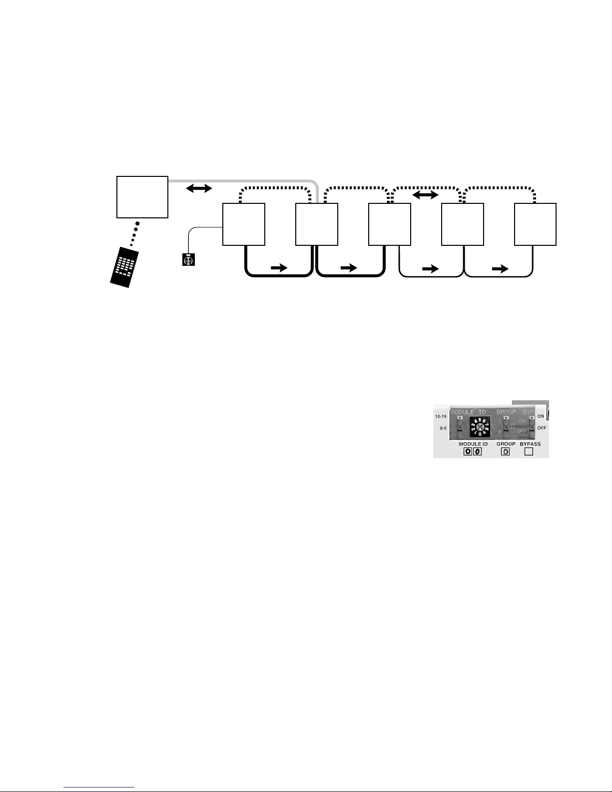
What is the Access™System?
The Access™ System consists of a variety of intelligent switching modules. These modules communicate with
each other via the “system bus,” allowing you to construct the exact demonstration system configuration you
desire from the sources, processors/equalizers, amplifiers, speakers, and subwoofers in your display. The
switching modules are located near the actual products on display creating a “distributed switching net-
work.” The products are connected to the modules rather than being wired to one central point. Selected
product signals are then sent across the network through “buses” that interconnect the modules. A simplified
view is shown below.
DEFINITION OF TERMS
To successfully install your new Access Demonstration Network, you should
familiarize yourself with the following terms:
Address A number that pinpoints the identity and location of a
switch module within a system. The installer sets numeric
switches like the ones in Figure for each module which
provides a unique address in the proper sequence for each
component connected to the system.
AutoDamping™When merchandising many pairs of different speakers in a
showroom, the drivers of the unselected speaker pairs
become passive radiators when the currently active
speaker pair is playing, absorbing much of the sound
coming from the speakers being played. AutoDamping™ is a circuit in the Model 93 that
electrically disconnects (shorts) speakers not being played, thereby automatically damping
them as passive radiators and improving sound quality in the showroom.
Bus A Bus is a pathway for signals to travel from module to module; a cable connecting
modules. There are three types of buses found in most AccessEZ Systems:
• System Bus A four wire harness (red, black, yellow, blue) connected to every
AccessEZ module. The System Bus carries the signals that control the selection of
the components and perform various housekeeping functions among the modules
in the system.
•Speaker Bus (or High Le el Bus) A four wire harness (green, white, brown, gray)
that carries speaker-level signals from source and/or amplifier modules to
speaker modules.
•Low-le el Bus A signal bus using RCA patch cables to carry low-level audio
signals between source modules and equalizer or amplifier modules.
Figure 1.
Figure 2. This example shows an
address setting of 0/00. Typically
this would represent the first
module (components 1 through 4)
in the Source Product Group.
Source
Switching
Module
System
Module
Amplifier
Switching
Module
Left
Speaker
Switching
Module
Right
Speaker
Switching
Module
SYSTEM BUS
SPEAKER BUS
Product
Select
Button
Remote
Control
Control
Panel
LOW LEVEL BUS
CONTROL PANEL CABLE

6
Bypass A way to hear a system without a particular in-line component (EQ, Crossover, Amplifier,
etc.). For example, when you wish to hear a system without the processor, the system can
route the signal past the processor group and directly to the amplifiers. In this expample,
Position #4 on the last module in the Processor Product Group is used as the bypass
location. When this position is selected, or the Product Group is deselected, the audio
signal continues through the bypassed group to the next Product Group. To activate
bypass, turn ON the Bypass switch only on the last module in the group.
Control Panel Control Panels, like the 90 , 903, 906 or AccessPC Touchscreen, add central control and
display capabilities to a system. Any control panel can operate hand-in-hand with prod-
uct select buttons.
Module A basic component of the AccessEZ™ System. There are five types of modules normally
found in car audio applications:
•Switching Modules select and connect products for demonstration and commu-
nicate with other system components through the System Bus. Examples are
Models 910D, 9 , 93 , 94 and 958.
•Expander Modules add channel capacity to switching modules. Examples are
Models 9 0X and 940X.
•System Modules perform basic control, interface and housekeeping functions
within the system. Examples include Models 980 and 988.
•DC Power Modules distribute DC power to sources, EQs, and amps. Examples
include Models 915X and 916X.
•Signal Distribution Modules, such as the 985EZ and 975, distribute audio and/or
video signals to output devices such as Video monitors.
Position The numbered point of connection (1-4 for electronics, or 1-8 for speakers) of a product to
a switching or expander module. The product select button (PSB) must be connected to
the corresponding position on the module. For example, if a component is connected to
position 3, its product select button must be connected to PSB position 3. When a “bypass”
is required, always use the fourth position (see “bypass”). Control Panels select positions
through the System Bus, and are not connected to individual positions.
Product Group A group of functionally similar products, such as sources, amplifiers, subwoofers, etc.
product group also refers to the windows to the right on 90 /903 control panels.
Product Select A push-button mounted at, or near the product location. Pushing this button selects the
Button (PSB) product for demonstration and lights an LED to confirm the selection.
System 1. A network of switching modules interconnected by buses where a control panel and/or
PSBs are employed to select and thereby interconnect specific components for demonstra-
tion. . A configuration of audio products or components playing together which can be
stored in control panel memory and A/B compared with other “systems.”
SilenTouch™ SilenTouch mutes the sound for a brief period during the switching process to eliminate
transient noises while changing from one product to the next.
TheftAlert™A special circuit that senses ground continuity of the products connected to the switching
modules. If an alarm device is connected to the system, it will sound if a product is
disconnected from the system without authorization. TheftAlert is an optional feature
available through your Audio Authority® Account Manager. TheftAlert may also be added
after your initial purchase. A special transformer is required for the feature to work and is
provided per your request. You then will need to install it in the proper position on the
switch modules.
7
942 932
922 980 932
Low Level Bus (Source Bus/Amp In Bus) Speaker Bus
Left Right
System Bus
HOW THE ACCESS™SYSTEM WORKS
When a product is selected for demonstration, signals are sent through a network of buses between switching
modules to activate that particular product position.
Selecting Products in the Access System
Products can be selected in a system in different ways that can all be combined into a single system, if desired.
You may select products in the following ways:
• By pressing a Product Select Button (PSB) connected to a switching module. This allows the user to build
different systems of product configurations manually.
• By using a control panel, if the system is so equipped. Control panel use is covered in detail in a separate
manual that accompanies each control panel.
• By issuing commands with the Model 905 IR Remote Control, which is included with the 90 Control
Panel and available with the 903. One 905 remote is recommended per salesperson.
• By using a computer touchscreen with AccessPC or custom software configured to enable product selec-
tions and other control functions.
• A combination of these methods.
Buses
Signals are passed between modules by “buses,” which are nothing more than cables that go from module to
module to module, connecting them into functional groups within the system’s architecture.
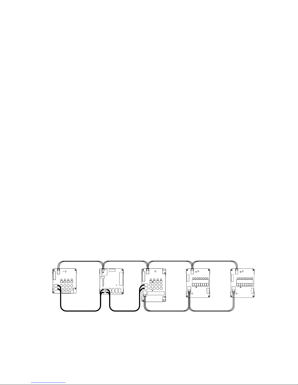
The System Bus connects all switching and system modules, allowing them to send messages to each other,
controlled by the addresses that are set by the installer. These signals instruct the modules to select the
inputs/outputs of a particular unit, such as a head unit or amplifier. Expander modules are not connected
directly to the System Bus. Each expander receives its instruction from the main switch module to which it is
attached.
Signal Buses carry audio signals, either low-level (source low-level output, for example) or high-level signals
(amplifier output).
Figure 3. Basic bus examples in a simple demonstration system.
8
ACCESS SYSTEM COMPONENTS
If you have already planned your system with the assistance of your account manager, you may wish to skip
directly to the Installation section. If you do not have a complete plan for your system, get help from your
Audio Authority® Account Manager by calling 800-3 -8346.
Access™User Interfaces
Control Panels
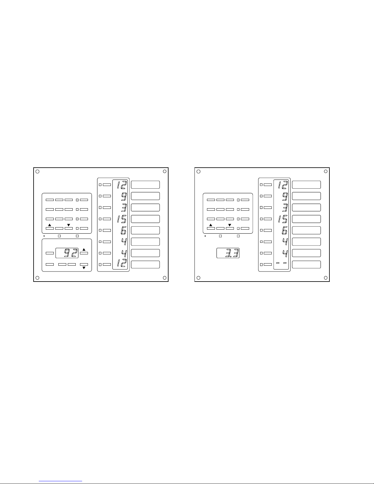
902 Full-Featured Control Panel
Includes one 987 Equal Volume Comparison (EVC) module, one microphone with 5’ cord, and one
905 IR Remote Control. Because the remote control serves such an essential function in a demonstra-
tion, one remote control is recommended for each sales person.
Figure 4. The 903 performs all the functions of the 902 except EVC and SPL AutoLimiting™, and the IR remote is optional.
902 Features include:
• Displays selected products, even when they are selected using Product Select Buttons or by remote
control. Displays diagnostic information for troubleshooting the system.
• Removable Product Group insert labels can be changed to indicate the functions of the LED
displays. An extensive set of labels is included with the control panel.
• Amplifiers can be connected to more than one Product Group allowing one amplifier to be demon-
strated independently as a front, rear, or sub amp (amp sharing).
• If not assigned as an active Product Group, the control panel’s last Product Group can store up to
99 pre-configured systems for immediate recall.
• Speakers with varying input sensitivities can be equalized to play at matched volumes by attenu-
ating the output level of the source. AutoCal™ program can run automatically or calibration
values can be directly written into the system’s memory.
• Optional TheftAlert™ circuit can be armed to sound an alarm should products on display be
disconnected without authorization.
FRONT AMP
FRONT SPEAKERS
REAR AMP
REAR SPEAKERS
ATTEN.
LEVEL
(STORE)
EQUAL VOLUME COMPARISON
ATTENUATION / SPL
DECIBELS
MUTE
(ADJUST) P-NOISE AUTO-CAL
Theft AlertSilenTouch
™
123
456
789
0
A
B
C
SECURE
ON / SPL
SUB AMP
HEAD UNITS
EQ/PROCESSORS
SUB SPEAKERS
ASD
å Demonstration Network
Patents Pending
Model 902 Control Panel
Theft AlertSilenTouch
™
123
456
789
0
A
B
C
SECURE
ASD
å Demonstration Network
Patents Pending
Model 903 Control Panel
FRONT AMP
FRONT SPEAKERS
REAR AMP
REAR SPEAKERS
SUB AMP
HEAD UNITS
EQ/PROCESSORS
SUB SPEAKERS
MODEL 902 FRONT PANEL MODEL 903 FRONT PANEL

9
• The control panel or any specific Product Group can be “locked out” from unauthorized user
input.
• Auto SPL controls the maximum volume level of the currently selected system. The maximum is
1 0 dB.
903 Control Panel
Similar to the 90 Control Panel, but does not include the 987 EVC module, so Equal Volume Com-
parison and Auto SPL are not available. The 905 IR Remote will operate the 903 Control Panel but is
not included, and must be purchased separately. All other functions of the 90 are inherent with the
903.
904 Product Group Expander for Control Panel
Adds eight additional Product Groups to your control panel. Up to 3 unique Product Groups can
exist in an Access™ System.
904V Product Group Expander and Volume Control
Adds four additional product groups to your control panel and provides a master volume control.
905 IR Remote
Full function Infrared Remote Control for 90 and 903 Control Panels.
906 Control Panel
Perfect for single product group displays such as subwoofer rooms or speaker walls, the 906 Control
Panel selects products using a rotary encoder knob, and displays the selected product number in the
LCD window. Use the Select Previous button to make instantaneous comparisons between products.
988CP0 Volume Control Panel
Provides master volume for Access demonstration systems.
Product Select Buttons and Indicators
Various button styles, sizes and colors are available. All have integrated LEDs to indicate when the
product is selected. Product indicators are simply LEDs mounted by each product showing which
products are playing.
Switching Modules
910D Head Unit Selector
Controls outputs from 4 source units for 4-channel high-level, -channel low-level operation. Pro-
vides DC power connection for each source. Module can be split in two for greater placement
flexibility using a Model 998 Extension Cable. Also features an expander port for adding additional
channels.
922 Low-Level Selector
Controls a pair of -channel low-level signals routed to or from 4 low-level products such as low-level
sources.
932 Speaker Selector
Accommodates 8 left OR 8 right speakers. Two 93 s are required for 8 stereo pairs. Non-selected
speakers are shorted to ground to reduce the sound absorption of unselected speakers in the display.

10
940EZ High-Level Selector
Controls two channel high-level signals routed to or from four high-level products. Controls two
channels of four products (e.g., high-level sources). Use Model 93 for applications where Au-
toDamping™ is desired.
942 2-Channel Amplifier Selector
Switches the low-level inputs and high-level outputs of four -channel amplifiers.
958 EQ or Crossover Selector
Controls low-level inputs and six channels of low-level outputs from four crossovers or equalizers.
System Module
980EZ
Provides the central point of control for DC power, SilenTouch™, 90 /903 Control Panel,
TheftAlert™ output, and so forth. The 980 is essential for any Access™ System and is typically
installed in the low-level signal path just prior to any amplifier inputs.
Expander Modules
920X and Low-Level Expansion Module
The 9 0X adds a pair of low-level channels to any switching module.
940X High-Level Expander Module
Adds a pair of high-level channels to any switching module.
System Specific Components
970 RS232 Serial Interface/PC Interface
Connects the Access system to a PC for computer control (Touchscreen, etc.).
971 Infrared Control Module
Customized to send IR commands to infrared audio and video components.
977 Digital Audio Adapters
977R converts optical digital audio signals to coax, and 977T converts coax digital audio signals to
optical.
975 FM Distribution Amplifier
1 -volt powered FM antenna booster drives all the radio antenna inputs and has direct input for one
or more RF output CD changers. Use with distribution components in Kit 16 or Kit 17. Kit 16 pro-
vides 4-way taps and cables for FM distribution to sixteen head units. Kit 17 contains one 4-way tap
and cables for four head units.
9A80 Crossover
A simple crossover which can be hidden inside the fixture, allowing two-channel low-level signal
from the headunit to be split for the demonstration of front speakers, rear speakers, and subwoofers.
981 DC Eliminator
Small, in-line, low-level device that eliminates DC that can be present in the low-level outputs of
some head units and crossovers found on the market. One required per offending product.
Inhaltsverzeichnis


