
Austa AU-1P3002G Bedienungsanleitung
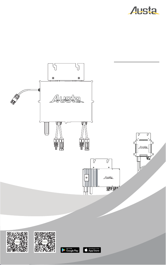
AU-1P4002G
AU-1P3002G AU-1P3502G
AU-1P6002G
MICROINVERTER SYSTEM
MIKRO-WECHSELRICHTER SYSTEM
USER MANUAL
BENUTZERHANDBUCH
Scan Here for Austa App
Search "Austa Solar"
on Google Play and App Store
Android ios
NINGBO AUSTA SOLAR TECH CO.,LTD
www.austasolar.net
AU-1P8002G AU-1P10002G
AU-1P16002G AU-1P20002G

General Introduction
Austa Microinverter User Manual 1
This system is composed of a group of microinverters that convert direct current (DC) into alternating
current (AC) and feed the power to the public grid. The system is designed for one microinverter is
connected with one or two PV modules.
Each microinverter works independently so as to guarantee the maximum power generation of each
PV module. This setup is highly fexible and reliable as the system enables direct control of the
production of each PV module.
About the Manual
This manual contains important instructions for AU-1P300/350/400/600/800/1000/1600/20002G
microinverters, for security reasons, please install or debuge the equipment after reading the
instructions in this maual carefully.
Other Information
Product information is subject to change without notice.
User manual will be updated regularly, so please refer to Ausat offcial website at www.austasolar.net
for the latest version.

CONTENTS
Austa Microinverter User Manual 2
1. Important Notes
2.1 Important Safety Instructions
2.2 Explanation of Symbols
1.1 Product Range
1.2 Target Group
1.3 Symbols Used
1.4 Electromagnetic interference statement
2. Safety Instructions
3. Product Introduction
4.1
Position and Space Required
4.2 How to Connect PV Modules to Microinverter
4.3 Installation Tools
4.4 AC Branch Circuit Capacity
3.1 About PV Inverter System
3.2 About Microinverter
4. Installation Preparation
5. Microinverter Installation
6. Troubleshooting
6.1 Troubleshooting List
6.2 LED Indicator Status
7. Technical Data
3
3
3
3
3
4
4
5
6
6
6
7
7
7
7
8
9
12
12
12
13
1.Important Notes
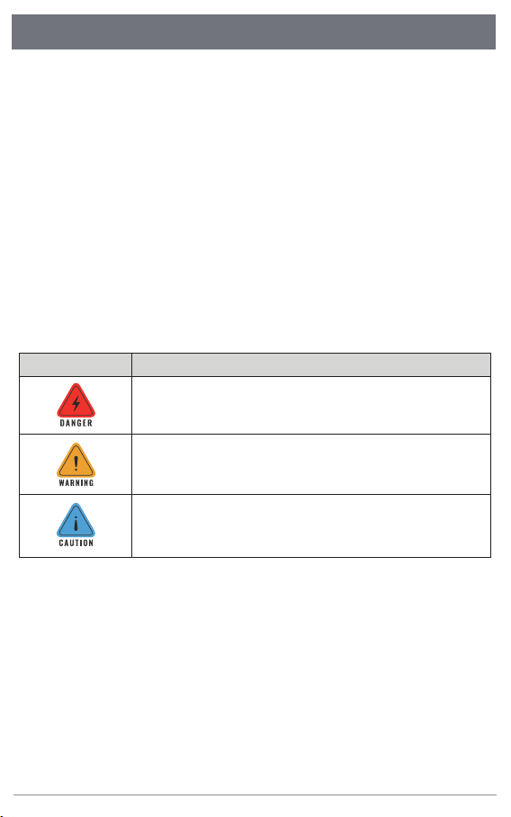
1.1 Product Ranges
1.2 Target Group
1.3 Symbols Used
1.4 Electromagnetic interference statement
This manual describes the assembly, installation, debuging, maintenance and troubleshooting of the
following models of Austa Microinverter AU-1P300/350/400/600/800/1000/1600/20002G
Note:
‶600”means 600W output.
The safety symbols in this user manual are shown as below.
This indicates a hazardous situation that can result in deadly electric shocks, ot
her serious physical injuries, or fre incidents.
This indicates that directions must be strictly followed to avoid safety hazards
including equipment damage and personal injury.
This indicates that the act is forbidden. You should stop, use caution and fully
understand the operations explained before proceeding
This microinverter has been tested and complies with the requirements of CE EMC, meaning that it
will not be afected by electromagnetic interference. Please note that incorrect installation may cause
electromag-neticdisturbances.
You can turn the equipment of and on to see if radio or television reception is interfered by this
equipment. If this equipment does cause harmful interference to radio or television, please try the
following measures to fix the interference:
Austa Microinverter User Manual 3
Austa micro inverters are designed for residential use and it has feature of quick installation.
Users must read and follow the instructions in this manual to install the inverter, no professional
installers are required.
However, if the feed power exceeds the upper limit allowed by the state, it must be installed by
professional installers
We strongly recommend that children or people lacking relevant knowledge not attempt to operate
this system
1)Relocate other apparatus' antenna.
2) Move the microinverter farther away from the antenna.
3) Separate the microinverter and the antenna with metal/concrete materials or roof.
4) Contact your dealer or an experienced radio/TV technician for help.
Austa Microinverter User Manual 4
2.Safety Instructions
2.1 Important Safety Instructions
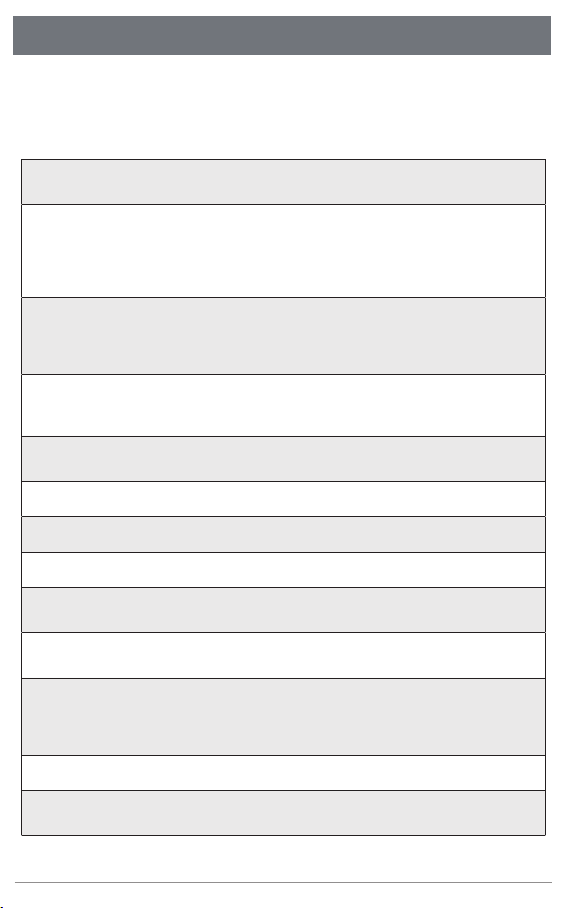
•
•
•
•
•
•
•
•
•
•
•
•
•
All operations including transportation, installation, start-up and maintenance must be carried outby
qualifed, trained personnel.
Check the product before installation to make sure there is no damage caused during transportation
because such damage can compromise the insulation integrity and safety clearances.
Choose installation location carefully and adhere to specifed cooling requirements. Unauthorized
removalof necessary protections, improper use, incorrect installation and operation may cause damage
to the equipment or incur serious safety and shock hazards.
You should get necessary approvals from local power operator before connecting the microinverter to the
power grid. This connection must be made only by qualifed technical personnel. It is the responsibility of
the installer to provide external disconnect switches and Over Current Protection Devices (OCPD).
Whenever the inverter has been disconnected from the public grid, please be extremely careful as some
components can retain charge sufcient to create a shock hazard. Before touching any part of the inverter,
please ensure the surface and the whole equipment are within the limit of safe temperature and voltage
potential.
Each input of the inverter is connected to one PV module. Do not connect batteries or other sources of
power supply. The inverter can be used only if all the technical parameters are observed and applied.
Do not install the equipment in flammable, explosive, corrosive, extremely hot/cold, and humid environm
-ent. Do not use the equipment when safety devices in these environments are not working.
Personal protective equipment such as gloves and goggles must be used during installation.
Inform the manufacturer about non-standard installation conditions.
Do not use the equipment if any operating anomalies are found.
Austa is not liable for any damage caused by incorrect or improper operation.
Electrical installation and maintenance shall be conducted by licensed electrician and shall comply with
local wiring rules
All repairs must be done with qualifed spare parts which must be installed in accordance with their inten
ded use and by a licensed contractor.
Liabilities arising from components that are not produced by Austa are on the part of their respective
manufacturers.
The AU-1P300/350/400/6002G microinverter is designed and tested according to international safety
require ments. However , certain safety precautions must be taken when installing and operating this
inverter. The installer must read and follow all instructions, cautions and warnings in this installation
manual.
Austa Microinverter User Manual 5
2.2 Explanation of Symbols
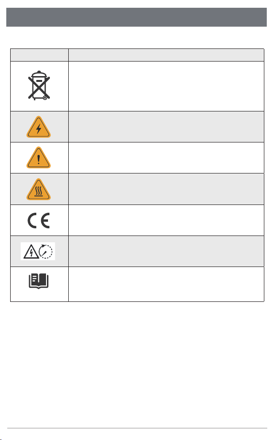
To comply with European Directive 2002/96/EC on Waste Electrical and Electronic
Equipment and its implementation as national law, electrical equipment that has
reached the end of its life must be collected separately and returned to an approved
recycling facility. Any device no longer needed must be returned to an authorized
dealer or approved collection and recycling facility.
Keep people out of 8 inches (20 cm) of the microinverter while it is operating.
Treatment
Caution
High voltage in the microinverter can cause dangers to life.
Danger of high voltage
The inverter can become hot during operation. Avoid contact with metal surfaces
during operation.
Beware of hot surface
The inverter complies with the Low Voltage Directive for the European Union &
2014/53/EU The Radio Equipment Directive (RED).
CE mark
Risk of electric shock,Energy storage timed discharge.
Caution
Please read the installation manual first before installation, operation and mainten-
ance.
Read manual first
2.Safety Instructions
3.Product Introduction
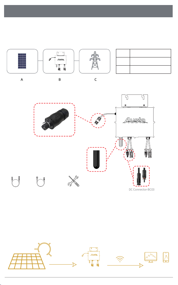
3.1 About PV Inverter System
3.2 About Microinverter
Screwdriver and wrenchDC Cable AC Cable/Schuko DC Connector-BC03
Wi-Fi Module
AC Connector-BC01
A typical grid-tied PV inverter system includes PV modules, PV inverter , and power grid , as shown be
low. PV inverter converts the DC power generated by PV modules into AC power that meets the requir
ements of the power grid. The AC power is then feed into the grid.
APV module
inverter
Power grid
B
C
Wi-Fi
App/Web
Microinverter
Note: See the bracket installation manual for more mounting accessories
Grid-tied PV system consists of PV panels, grid-tied inverter. The DC output from the PV panels is con
verted into AC energy and feedback tothe grid through the AU-1P300/350/400/6002G. AU-1P300/350/
400/6002G PV micro inverter contains isolation transformer with basic insulation between PV input
and AC grid output. This manual provides detailed product information and installation instructions
for the AU-1P600/8002G micro inverter. Please read through this manual before installation and
operation.
Austa Microinverter User Manual 6
4.Installation Preparation
4.1 Position and Space Required
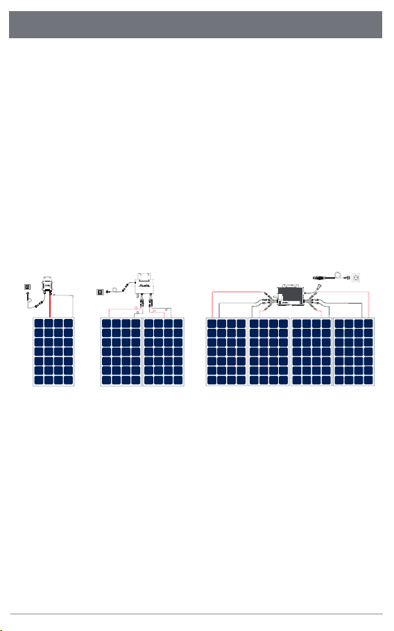
4.2 How to Connect PV Modules to Microinverter
Please install the microinverter and all DC connections under the PV module to avoid direct sunlight,
rain exposure, snow buildup, UV etc. The silver side of the microinverter should be up and facing the
PV moduleLeave a minimum of 2 cm of front side the microinverter enclosure to ensure ventilation
and heat dissipation.
General Guidelines:
1. PV modules should be connected to DC input ports of a microinverter.
2. Use DC cable . Please consult the local power opera-tor to make sure that the DC cable complies
with local regulations.
The typical wiring method is shown below.
The voltage of modules (considering the effect of local temperature) must not exceed the maximum
input voltage of the microinverter. Otherwise, the microinverter maybe damaged.
(refer to theTechnical Data section to determine the absolute maximum input voltage).
Note:
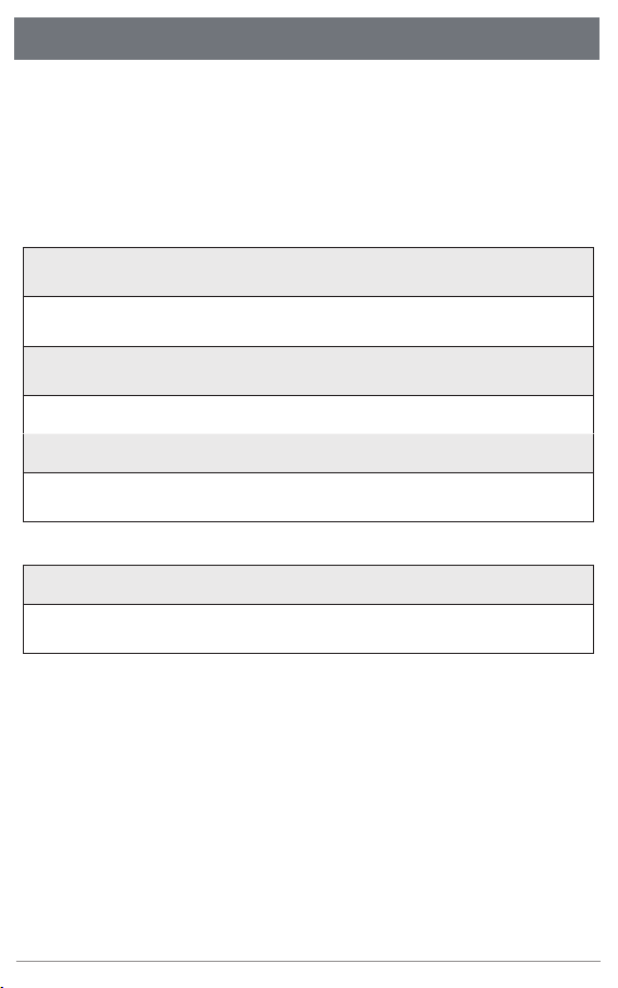
4.3 AC Branch Circuit Capacity
Note:
1. Microinverters can be connected to the same AC branch, as long as the total currentdoes not exceed
the ampacity specifed in local regulations.
The Austa AU-1P300/350/400/600/800/1000/1600/20002G can be paralleled using the paralleling
interface on the microinverter. The number of microinverters on the AC branch must not exceed the
limits. Do not exceed the maximum number of microinverters in the AC branch circuit, as indicated on
the unit rating label. For 12AWG trunk cables, each microinverter's AC branch circuit must come from
a dedicated branch circuit protected by a 20A maximum circuit breaker.
The Austa microinverter system is designed to connnect max four PV modules.
AU-1P300/350/4002G can connect one PV module. AU-1P600/8002G can connect two PV modules.
AU-1P1000/1600/20002G can connect four PV modules.
The inverter can support over matching 1.5 times, such as AU-1P6002G can connect max 900W PV
modules input.
Austa Microinverter User Manual 7
4.Installation Preparation
4.4 Precautions
The equipment is installed based on the system design and the location .
2. Ensure that protective end caps are installed on all unused AC connectors. Unused AC harness
connectors are energised when the system is powered up.
3. AU-1P300/350/4002G supports up to maximum 11 units branch. AU-1P6002G supports up to
maximum 6 units branch. AU-1P8002G supports up to maximum 5 units branch. AU-1P10002G
supports up to maximum 3 units branch. AU -1P1600/20002G supports up to maximum 2units branch.
•
•
•
•
•
•
•
•
The installation must be done with the equipment disconnected from the grid (power disconnect
switch open) and with the PV modules shaded or isolated.
Make sure the environmental conditions of the microinverter’s requirement (degree of protection,tem
perature, humidity, altitude, etc.) as specifed in the Technical Data section.
Avoid direct sunlight to prevent power derating which can be caused by an increase in the internal
temperature of the micro inverter.
Keep the inverter in well-ventilated place to avoid over heating.
Keep the inverter away from gases or fammable substances.
Avoid electromagnetic interference because it can compromise the normal operation of electronic
equipment.
Install only on structures specifcally designed for PV modules (supplied by installation technicians).
Install microinverter underneath PV modules to make sure it works in the shadow. Nonobservance
may cause the derating of inverter production.
Installation location shall meet the following conditions:
Austa Microinverter User Manual 8
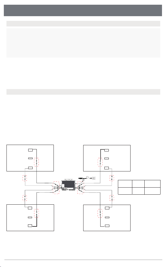
Note:
The voltage of modules (considering the effect of local temperature) must not exceed the maximum
input voltage of the microinverter. Otherwise, the microinverter maybe damaged (refer to the
Technical Data section to determine the absolute maximum input voltage).
5.Microinverter Installation
Step 1. Plan and Install the Microinverter
Step 2. Connect PV Modules
Note:
1.Microinverter installation and DC connections must be done under the PV module to avoid direct
sunlight,rain exposure, snow buildup, UV etc.
2.Leave a minimum of 2 cm of space around the microinverter enclosure to ensure ventilation and
heat dissipation.
Note:
1. Make sure that the AC Connectors are kept away from any drainage channels.
2. In case you need to remove the microinverter AC cable from interface, Removal is accomplished by
inserting an MC4 spanner into the side connector.
3. The order of Step 1 and Step 2 can be reversed according to your planned needs.
Before you install, you should have the following devices:
MicroInverter
Required photovoltaic modules
Mounting brackets according to your installation design
AC cable and solar cables that meet your requirements in length
Suitable installation tools and no less than 2 people
A) Mount the PV modules above the microinverter.
B) Connect the PV modules’ DC cables to the DC input side of the microinverter. Wait five minutes
and you'll see the LED will turn red and flashing.
A B C
PV module DC cable Microinverter
Austa Microinverter User Manual 9
1
2
3
+
-
+
-
+
-
+
-
Dieses Handbuch passt für folgende Modelle
7
Inhaltsverzeichnis
Sprachen:
Andere Austa Wechselrichter Handbücher


