Autocall A100-3109 IDNet 2 Bedienungsanleitung

Cautions, warnings, and regulatory information
READ AND SAVE THESE INSTRUCTIONS Follow the instructions in this installation manual. These instructions must be followed to avoid damage to
this product and associated equipment. Product operation and reliability depend upon proper installation.
DO NOT INSTALL ANY AUTOCALL™ PRODUCT THAT APPEARS DAMAGED Upon unpacking your Autocall product, inspect the
contents of the carton for shipping damage. If damage is apparent, immediately file a claim with the carrier and notify an authorized
Autocall product supplier.
ELECTRICAL HAZARD Disconnect electrical field power when making any internal adjustments or repairs. All repairs should be
performed by a representative or an authorized agent of your local Autocall product supplier.
STATIC HAZARD Static electricity can damage components. Handle as follows:
• Ground yourself before opening or installing components.
• Prior to installation, keep components wrapped in anti-static material at all times.
EYE SAFETY HAZARD Under certain fiber optic application conditions, the optical output of this device may exceed eye safety limits. Do
not use magnification (such as a microscope or other focusing equipment) when viewing the output of this device.
SULFURIC ACID WARNING Battery contains sulfuric acid, which can cause severe burns to the skin and eyes and can destroy fabric.
Replace any leaking or damaged battery while wearing appropriate protective gear. If you come in contact with sulfuric acid, immediately
flush skin or eyes with water for 15 minutes and seek immediate medical attention.
FCC RULES AND REGULATIONS – PART 15 This equipment has been tested and found to comply with the limits for a Class A digital device, pursuant
to Part 15 of the FCC Rules. These limits are designed to provide reasonable protection against harmful interference when the equipment is operated
in a commercial environment. This equipment generates, uses, and can radiate radio frequency energy and, if not installed and used in accordance
with the instruction manual, may cause harmful interference to radio communications. Operation of this equipment in a residential area is likely to
cause harmful interference in which case the user will be required to correct the interference at his own expense.
SYSTEM REACCPTANCE TEST AFTER SOFTWARE CHANGES To ensure proper system operation, this product must be tested in accordance with
NFPA-72, after any programming operation or change in site-specific software. Reacceptance testing is required after any change, addition or deletion
of system components, or after any modification, repair or adjustment to system hardware or wiring. All components, circuits, system operations, or
software functions known to be affected by a change must be 100% tested. In addition, to ensure that other operations are not inadvertently affected,
at least 10% of initiating devices that are not directly affected by the change, up to a maximum of 50 devices, must also be tested and proper system
operation verified.
NFPA 72® is a registered trademark of the National Fire Protection Association.
Introduction
The IDNet 2* card provides the Fire Alarm Control Panel (FACP) with one
isolated IDNet Signaling Line Circuit (SLC) (or channel) and with up to
four isolated loop outputs. This card is used with compatible** IDNet
communicating devices and allows the system CPU to communicate with
up to 250 initiating devices, such as smoke sensors and pull stations.
Isolated IDNet communications provide overall operation improvement,
and isolated output loops allow a short circuit on one loop to avoid
impacting the other loops.
There are two available configurations for the IDNet 2 card:
• A100-3109 IDNet 2 card: This is the basic configuration which
provides the FACP with two Class B / DCLB (or Class A / DCLA or
Class X / DCLC) loop outputs that are isolated from each other as
well.
• A100-3110 IDNet 2+2 card: In this configuration, the A100-3109
IDNet 2 card is fitted with two A100-3111 IDNet Loop cards and
provides the FACP with four Class B / DCLB (or Class A / DCLA
or Class X / DCLC) isolated IDNet loops. Two isolated loops are
provided by the card and one isolated loop is added per IDNet
Loop card.
*= Unless specified otherwise, the term “IDNet 2” is used in this manual to
designate both the IDNet 2 and the IDNet 2+2 cards.
Note: The A100-3111 IDNet Loop daughter card can be purchased separately and placed on a pre-installed IDNet 2 card that is not EPS-mounted.
However, once it is added to the IDNet card, the compatibility and programming requirements will become the same as with the IDNet 2+2 card.
Important: Verify FACP system programmer, executive, and slave software compatibility when installing, or replacing system components. Refer to the
Technical Support Information and Downloads website for compatibility information.
579-1169AC Rev. F
A100-3109 IDNet 2, A100-3110 IDNet 2+2 and A100-3111 IDNet Loop card Installation Instructions
*05791169ACF*

Card Layout
Compatibility
Hardware compatibility:
IDNet 2: 4100ES bays, EPS modules, 4100U bays.
IDNet 2+2: 4100ES bays, 4100U bays, ES-PS modules.
Software compatibility:
For use with revision 2.04 or higher of the ES Panel Programmer Software, and revision 12.08 of the 4100U Programmer and Master software.
Card Layout
The IDNet 2 is a standard 4x5 card that can accommodate two IDNet Loop cards. Figure 1 highlights the feature elements of these cards.
Figure 1: Card Layout
page 2 579-1169AC Rev. F
A100-3109 IDNet 2, A100-3110 IDNet 2+2 and A100-3111 IDNet Loop card Installation Instructions

LED Identification
The IDNet 2 Card is equipped with 8 LEDs that report the card troubles. Table 1 identifies and describes the different LEDs.
Table 1: LED Definition
LED Name LED description LED Map
Loop A
Loop B
Loop C
Loop D
When a trouble occurs on a loop, the LED corresponding to that loop
illuminates.
Earth- Normally Off. Illuminates to indicate a negative earth fault.
Earth+ Normally Off. Illuminates to indicate a positive earth fault.
IDNet Normally off. Illuminates to indicate a problem with the IDNet channel:
• Steady on indicates channel failure.
Comms Normally off. Turns on steady if the card is not communicating with the
FACP CPU.
Setting the Address
The DIP Switch SW1 is used to set the IDNet 2 card address as identified in the Panel Programmer job (see the section on Programming for more
information). From left to right, these switches are designated as SW1-1 through SW1-8. The function of these switches is as follows:
• SW1-1. This switch sets the baud rate for the internal communications line running between the card and the CPU. Set this switch to ON.
• SW1-2 through SW1-8. These switches set the card’s address within the FACP. Refer to Figure 3 for a complete list of the switch settings for all
of the possible card addresses.
You must set these switches to the value assigned to the card by the Panel Programmer.
Figure 2: DIP Switch SW1
page 3 579-1169AC Rev. F
A100-3109 IDNet 2, A100-3110 IDNet 2+2 and A100-3111 IDNet Loop card Installation Instructions

Figure 3: A100-3109 IDNet 2 Card Addresses
page 4 579-1169AC Rev. F
A100-3109 IDNet 2, A100-3110 IDNet 2+2 and A100-3111 IDNet Loop card Installation Instructions

Installation
Mounting
The IDNet 2 card and the IDNet 2+2 card mount onto the Power Distribution Interface (PDI) in an FACP expansion cabinet. The IDNet 2 card can also
be installed in the expansion slot of an ES Power Supply Card (ES-PS) card.
To mount the IDNet 2 and IDNet 2+2 card:
1. Select an empty PDI connector. Insert the washer and the metal standoffs into the corresponding installation holes.
2. Insert the PDI connector on the back of the card into the PDI connector.
3. Use the provided hardware to secure the card.
Figure 4: Mounting an IDNet 2 or IDNet 2+2 card (IDNet 2 card shown)
To add IDNet Loop cards to an IDNet 2 card:
1. Remove the screws that attach the IDNet 2 card to the panel.
2. Insert the metal standoffs and the plastic standoffs into the corresponding installation holes.
3. Insert the connector on the back of the IDNet Loop card into the connector on the IDNet 2 card and snap it in place with the plastic standoff.
4. Use the provided hardware to secure the card.
Note: When adding IDNet Loop cards to a pre-installed IDNet 2 card, it is important to remember that the properties of the IDNet 2 card must be
updated in the FACP programmer.
Figure 5: Adding an IDNet Loop Card to an IDNet 2 Card
page 5 579-1169AC Rev. F
A100-3109 IDNet 2, A100-3110 IDNet 2+2 and A100-3111 IDNet Loop card Installation Instructions

Wiring Overview
Each IDNet output from the IDNet 2+2 card can be wired as either an isolated Class A / DCLA circuit, a Class X / DCLC circuit, or as two isolated Class
B / DCLB circuits.
Class A / DCLA wiring provides an alternate communication path that allows communication to all devices to be maintained when a single open
circuit fault occurs. Class A wiring requires two wires to be routed from the Primary Terminals (B+, B-) to each device, and then back to the Secondary
Terminals (A+, A-). Wiring is in/out, “T” tapping is not allowed.
Class B / DCLB wiring allows “T” tapping. IDNet wiring is inherently supervised due to individual device level communications. End-of-line resistors are
not required.
Class X / DCLC wiring improves on Class A wiring by providing resilience not only to single open fault but also to a single short-circuit fault. Use IDNet
Isolator or Isolator2 devices.
Ferrite Beads
You must use ferrite beads for field wiring. To install ferrite beads, complete the following steps:
1. Install a ferrite bead near any IDNet field wiring terminals in use (terminals B+/B- or terminals A+/A-) for the lowest radiated emissions. Install
the ferrite bead at a place before the wires leave the enclosure.
2. Loop the wires through the bead as shown in Figure 6.
Figure 6: Ferrite bead installation
Wiring Parameters
Table 2 identifies the card wiring parameters that must be considered when installing these cards.
Table 2: Card Wiring Parameters
Wiring Capacitance Parameters
Parameter Value
Maximum Supported Channel Capacitance; Total of all four Isolated
Outputs.
The sum of line-to-line capacitance, plus the capacitance of either line-to-shield
(if shield is present) = 0.6 μF (600 nF).
Capacitance between IDNet SLC wiring (between wires of the same
polarity; plus to plus, minus to minus).
1 μF maximum (this is for multiple IDNet loops).
Wiring Distance Limits (see note below).
Class B Wiring, Total Channel Wiring Parameters,
Including T-Taps
Class A or X Wiring, Total Channel Wiring
Parameters
Channel Loading
Up to 125 devices 126 to 250 devices Up to 125 devices 126 to 250 devices
Total Loop Resistance 50 Ω maximum 35 Ω maximum 50 Ω maximum 35 Ω maximum
18 AWG (0.82 mm2) 4000 ft (1219 m) per run,
12,500 ft (3810 m) total
2500 ft (762 m) per run,
10,000 ft (3048 m) total
4000 ft (1219 m) per loop,
12,500 ft (3810 m) total
2500 ft (762 m) per loop,
10,000 ft (3048 m) total
16 AWG (1.31 mm2)
14 AWG (2.08 mm2)
12 AWG (3.31mm2)
5000 ft (1524 m) per run,
12,500 ft (3810 m) total
2500 ft (762 m) per run,
10,000 ft (3048 m) total
5000 ft (1524 m) per loop,
12,500 ft (3810 m) total
2500 ft (762 m) per loop,
10,000 ft (3048 m) total
Note: Maximum wiring distance is determined by either reaching the maximum resistance, the maximum capacitance, or the stated maximum
distance, whichever occurs first. Class A or X maximum distances are to the farthest device on the loop from either “B” or “A” terminals. For Class B
wiring, the maximum distance to the farthest device is limited to the stated Class A or X wiring distances.
Note: External wiring must be shielded (for lightning suppression) and A2081-9044 Overvoltage Protectors
must be installed at building exit and entrance locations.
Capacitance: Each protector adds 0.006 μF across the connected line.
Resistance: Each protector adds 3 Ω per line of series resistance; both IDNet lines are protected; 6 Ω per
protector will be added to total loop resistance.
Maximum distance of a single protected wiring run is 3270 ft (1 km).
Wiring Considerations using
A2081-9044 Overvoltage Protectors.
(A2081-9044 is UL listed to Standard
1459, Standard for Telephone
Equipment).
Refer to document number 574-832AC: A2081-9044 Overvoltage Protector Installation Instructions for additional
information.
page 6 579-1169AC Rev. F
A100-3109 IDNet 2, A100-3110 IDNet 2+2 and A100-3111 IDNet Loop card Installation Instructions

Class A / DCLA Wiring
To wire the Loop terminals as a Class A circuit:
1. Set the jumper assigned to the loop to the “A” position, as shown in Figure 7.
- Loop A= Jumper P1 on the IDNet 2 card
- Loop B= Jumper P2 on the IDNet 2 card
- Loop C= Jumper P1 on the first IDNet Loop cards
- Loop D= Jumper P1 on the second IDNet Loop card
2. Shielded wire is not recommended. If shielded wires are present, cut and tape off the shield to
prevent it from coming in contact with other components. Metallic continuity of the shield must
be maintained and insulated throughout the entire length of the cable.
3. Route the wiring from the Primary Terminals (B+, B-) to the corresponding inputs on the first
device.
4. Route wiring from the first device to the next as in/out. See Figure 8. Repeat for each device.
5. Route the wiring from the last device to the panel.
6. Connect the wiring to the corresponding Secondary Terminals (A+, A-).
Figure 7: Class A Jumper Setting
Figure 8: IDNet Loop Class A Wiring
Class A wiring notes:
• If no remote isolators or isolator bases are on the loops, you can assign device addresses in any sequence.
• If remote isolators (A4090-9116, A4090-9122) or isolator bases (A4098-9766, A4098-9767, A4098-9777, A4098-9793) are on the loops, it is
recommended to address the isolators in ascending order: start from the “B” side and assign each successive isolator a higher address than
the isolator it preceeds. Isolation functionality is not affected by the order of isolator addresses.
• If there are any remote isolators (A4090-9116) or isolator bases (A4098-9777, A4098-9793) on the channel, addressing the isolators as
recommended speeds up the system power up.
• If there are only isolator2 (A4090-9122) or isolator2 bases (A4098-9766, A4098-9767) on the channel, addressing the isolators as
recommended speeds up the Earth Fault Search diagnostic tool.
• Regular IDNet devices (that are not isolators A4090-9116, A4090-9122, A4098-9777, A4098-9793, A4098-9766, A4098-9767) can be addressed
in any way without impact.
page 7 579-1169AC Rev. F
A100-3109 IDNet 2, A100-3110 IDNet 2+2 and A100-3111 IDNet Loop card Installation Instructions
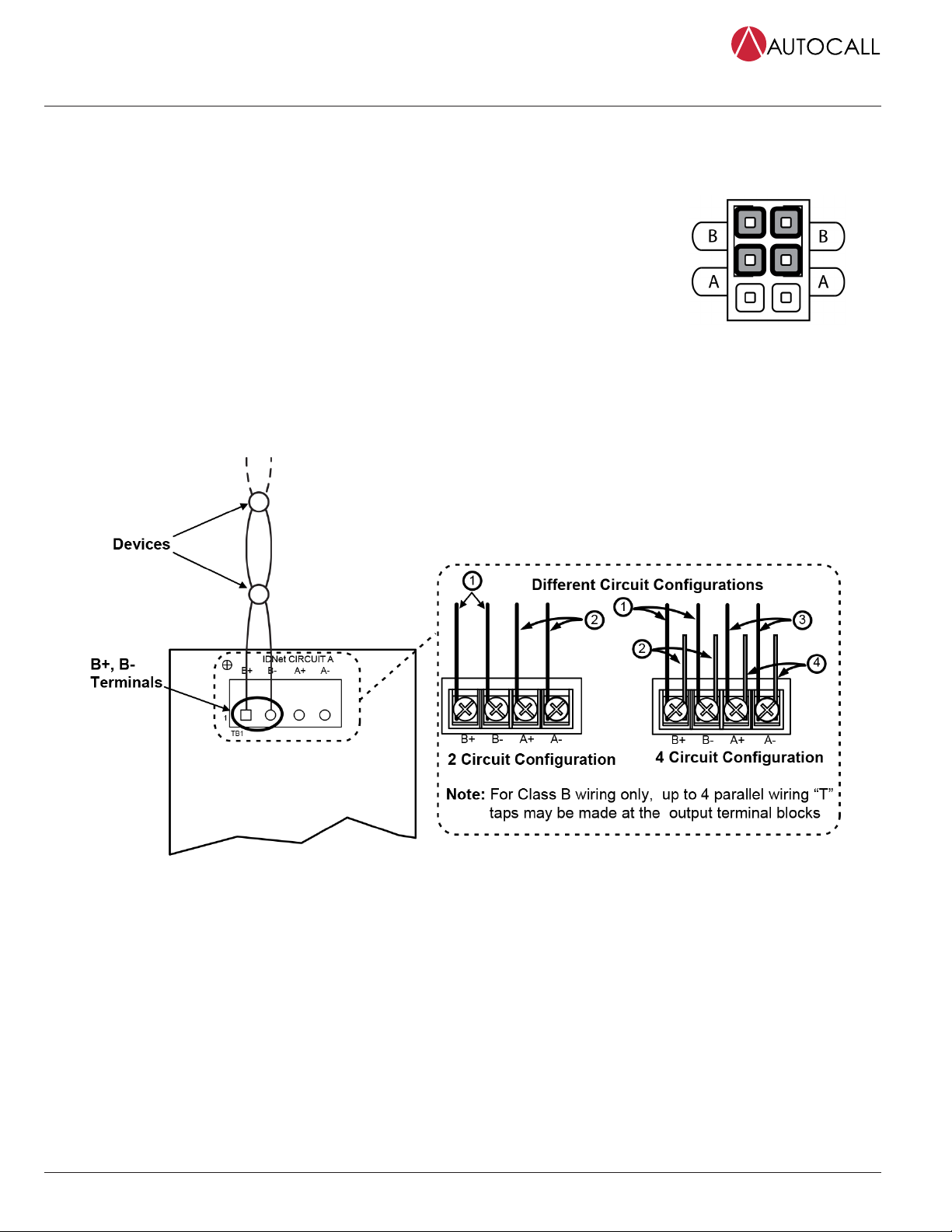
Class B / DCLB Wiring
When wiring the loop for Class B circuits, both the B+, B- and A+, A- terminals are available for parallel connections. Within the IDNet circuitry, A+ is
connected to B+, and A- is connected to B- so circuits can stem from either one. Additionally, two wires can be connected to each screw terminal.
To wire the Loop terminals as a Class B circuit:
1. Set the jumper assigned to the loop to the “B” position, as shown in Figure 9.
- Loop 1 = Jumper P1 on the IDNet 2 card
- Loop 2 = Jumper P2 on the IDNet 2 card
- Loop 3 = Jumper P1 on the left IDNet Loop card
- Loop 4 = Jumper P1 on the right IDNet Loop card
2. Route wiring from the Primary Terminals (B+, B-) to the corresponding inputs on the first device.
It is possible to add up to 4 circuits per IDNet loop on the terminal block when using Class B wiring.
See Figure 10 for the diagram.
3. Route wiring from the first device to the next as in/out as shown in Figure 10. Repeat for each
device.
4. Shielded wire is not recommended. If shielded wires are present, cut and tape off the shield at each
end (in the panel and at the last device in each run) to prevent it from coming in contact with other
components. Metallic continuity of the shield must be maintained and insulated throughout the
entire length of the cable.
Figure 9: Class B Jumper Setting
Figure 10: IDNet Loop Class B Wiring
Class B wiring Notes:
• If no remote isolators or isolator bases are on the loops, you can assign device addresses in any sequence.
• If remote isolators (A4090-9116, A4090-9122) or isolator bases (A4098-9766, A4098-9767, A4098-9777, A4098-9793) are on the loops, it is
recommended to address the isolators in ascending order: start at the output and assign each successive isolator a higher address than the
isolator it preceeds. For Class B wiring only, the “A” output and “B” output per loop are connected together in parallel for wiring convenience.
Isolation functionality is not affected by the order of isolator addresses.
• If there are any remote isolators (A4090-9116) or isolator bases (A4098-9777, A4098-9793) on the channel, addressing the isolators as
recommended speeds up the system power up.
• If there are only isolator2 (A4090-9122) or isolator2 bases (A4098-9766, A4098-9767) on the channel, addressing the isolators as
recommended speeds up the Earth Fault Search diagnostic tool.
• Regular IDNet devices (that are not isolators A4090-9116, A4090-9122, A4098-9777, A4098-9793, A4098-9766, A4098-9767) can be addressed
in any way without impact.
Class X / DCLC Wiring
To wire the loop terminals as a Class X circuit, follow Class A / DCLA Wiring guidelines and insert IDNet Isolator or Isolator2 devices along the loop.
page 8 579-1169AC Rev. F
A100-3109 IDNet 2, A100-3110 IDNet 2+2 and A100-3111 IDNet Loop card Installation Instructions

Programming
Adding the IDNet 2 to the Programmer
The IDNet 2 card must be added to the FACP through the ES Panel Programmer.
Note:
The IDNet 2+2 card can be added to the programmer using the same steps as shown below. The difference is in selecting the A100-3110/A100-3112
IDNet 2+2 card from the Available Hardware window instead of the A100-3109 IDNet 2 card.
Note: To add the IDNet 2 card to the programmer:
1. Start the programmer software.
2. Open an existing job or create a new one.
3. Select the Hardware tab.
4. Open the Box and the Bay in which you want to place the card.
5. Select the A100-3109 IDNet 2 card from the Available Hardware window under the “Interface” menu and drag it to the bay. The card has now been
added to your FACP.
6. Double click on the card’s icon to access the Card Properties, Point Editing and Loop Editing tabs. See the “Configuring the Card Properties
Tab” section for more information.
Figure 11: Adding the IDNet 2 Card to the FACP
Configuring the Card Properties Tab
The first tab that require configuring is the Card Properties tab.
To configure the Car Properties tab enter the following information:
• Card Address.*
• Card Description.
• Card Default label.
• Card Custom Label: This field can be used to describe the
card's function, location, or other descriptive information.
• Card Alternate Custom Label: This field is used to have an
alternative description of the card.
• Annunciator: This field indicates which annunciator the card
is associated with.
• Number of units, bays, and boxes.*
• Location.*
• Only activate TrueAlarm device LEDs**: Select this option to only
activate the LEDs corresponding to TrueAlarm devices in a state of
alarm (up to 20 devices at any given time).
• Activate Signal IAM LEDs**: Select this option to only activate the
LEDs corresponding to Signal IAM devices that are in a state of alarm
(up to 20 devices at any given time).
• 24 V Alarm and Standby current (Amps).
* It is possible to modify the default data manually, however, an error will be triggered if the information entered does not correspond with the FACP
data.
** These options are independent of each other, either one or both can be selected.
page 9 579-1169AC Rev. F
A100-3109 IDNet 2, A100-3110 IDNet 2+2 and A100-3111 IDNet Loop card Installation Instructions

Figure 12: Card Properties Tab
page 10 579-1169AC Rev. F
A100-3109 IDNet 2, A100-3110 IDNet 2+2 and A100-3111 IDNet Loop card Installation Instructions
Dieses Handbuch passt für folgende Modelle
2
Inhaltsverzeichnis
Beliebte Computerhardware Handbücher anderer Marken

EMC2
EMC2 VNX Series Betriebsanleitung

Panasonic
Panasonic DV0PM20105 Bedienungsanleitung

Mitsubishi Electric
Mitsubishi Electric Q81BD-J61BT11 Bedienungsanleitung

Gigabyte
Gigabyte B660M DS3H AX DDR4 Bedienungsanleitung

Raidon
Raidon iT2300 Bedienungsanleitung

National Instruments
National Instruments PXI-8186 Bedienungsanleitung


