
Avid Technology MEDIAswitch Bedienungsanleitung

MEDIAswitch
For MediaShare Fibre Channel

2
MediaShare F/C Overview ........................................................................................3
MediaShare F/C Components........................................................................................................ 3
Installing the MediaShare F/C Switch....................................................................5
Attaching the Slide Rails............................................................................................................... 5
Mounting the Switch..................................................................................................................... 5
Connecting Cables to the Switch................................................................................................... 5
Connecting Avid Systems ............................................................................................................. 6
Connecting MSDEs ...................................................................................................................... 6
Creating a Daisy-Chain of MSDEs................................................................................................ 7
Powering Up the System............................................................................................................... 7
Troubleshooting.........................................................................................................8
POST Diagnostics......................................................................................................................... 9
LED Indications...........................................................................................................................10
Common Questions and Problems................................................................................................11
How to Connect to the MEDIAswitch...................................................................13
Overview.....................................................................................................................................13
Ethernet Connection ....................................................................................................................13
Host-to-MEDIAswitch SLIP Connection......................................................................................13
Microsoft Windows NT 4.0 SLIP Configuration...........................................................................14
Windows NT 4.0 SLIP Connection ..............................................................................................18
Loop InSite: Introduction........................................................................................20
Product Overview ........................................................................................................................20
Features.......................................................................................................................................20
Loop InSite: Installation (and Removal)..............................................................21
Software Installation....................................................................................................................21
Software Removal........................................................................................................................21
Loop InSite: Site View and Overview...................................................................22
Real Time Status of Fibre Channel Site ........................................................................................22
Color Coding Priorities and Indications........................................................................................22
Loop InSite: Front Panel Information Display....................................................24
Pull Down Options ......................................................................................................................24
Loop InSite: Configuration.....................................................................................27
Logging Tab................................................................................................................................27
Stealth Tab ..................................................................................................................................28
Zoning Tab..................................................................................................................................30
Diagnostic Mode.......................................................................................................32
Diagnostic Options ......................................................................................................................33
Specifications...........................................................................................................34
LED Indicators ............................................................................................................................34
Physical Dimensions....................................................................................................................34
Power Requirements....................................................................................................................34
Environmental Conditions............................................................................................................34
Data Transmission Range and Interconnects.................................................................................34

3
MediaShare F/C Overview
Avid MediaShare F/C (Fibre Channel) provides a shared storage subsystem for up to six Avid
systems (Media Composer, Film Composer, Media Station, or Avid Xpress for Macintosh
systems). MediaShare F/C allows all six users to simultaneously read the same shared media
files, while only one of the users can write changes to the files on a drive partition.
MediaShare F/C Components
MediaShare F/C uses a number of components to make up the storage subsystem. Each
MediaShare F/C storage subsystem is composed of:
•One MediaShare F/C controller board for each Avid system that is connecting to the
MediaShare F/C storage subsystem
•One or more MediaShare F/C drive enclosures (MSDE) that contain the drives for storing
media files
•One MediaShare F/C MEDIAswitch for connecting up to six Avid systems to the MediaShare
F/C MSDEs
•Several MediaShare F/C cables for connecting the components
•The MediaShare F/C software for setting up and controlling the MediaShare F/C environment
MediaShare F/C Controller Board
Each Avid system that connects to the MediaShare F/C storage subsystem needs a MediaShare
F/C controller board. This board allows the Avid system to mount the MediaShare F/C drives
and access the media files and other data stored on the drives in the MSDE through the
MediaShare F/C MEDIAswitch.
MediaShare F/C Drive Enclosure
The MediaShare F/C drive enclosure holds the files channel drives that store data in the
MediaShare F/C environment. Each MediaShare F/C storage subsystem has at least one
MSDE. You can connect several MSDEs together to expand the capacity of the storage
subsystem. Each MediaShare F/C MSDE contains:
•Up to ten MediaShare F/C drives. The drives can be partitioned to segregate the data for
different projects or users, and they can be striped to provide increased performance.
•One link control card (LCC). The LCC supports and controls the files channel loop, and
monitors the enclosure environment.
•Two power supplies. Each power supply can support a fully configured MSDE. The two
power supplies provide automatic power redundancy should one of the power supplies fail.
The MSDE is available in two models:
•A rack-mount model. This model fits into a standard 19-inch NEMA or EIA rack and comes
with a set of mounting rails to support the MSDE.

4
•A 10-slot deskside model. This model supports one MSDE in a roll-around deskside cabinet.
MediaShare F/C MEDIAswitch
The MediaShare F/C switch is a Fibre Channel switch with 8 ports that allow you to connect up to
six Avid systems and two groups of MediaShare drive enclosures (MSDEs) together. The switch
is used in place of the hub to connect the systems and storage for the MediaShare F/C
environment.
The MediaShare F/C switch isolates its ports, treating the port as an individual Fibre Channel
loop. This isolation localizes loop initialization events, such as adding or removing system or
system restarts, to a particular port and increases the Fibre Channel environment stability.
MediaShare F/C Cables
MediaShare F/C uses copper cables to connect the Avid systems and the MediaShare F/C
MSDEs to the MEDIAswitch. Copper cables are fully shielded, 75 ??(ohm), twin-axial cables
with the shield fully bonded to a DB-9 connector at each end. They can be used when the
distance from the Avid system to the hub or the hub to the MediaShare F/C MSDEs does not
exceed 99 feet (30 meters). Cop- per cables must meet the 1-GBd FC-AL standard, revision 4.4
or higher. Cable lengths of 10 meters and longer must be equalized.
You cannot splice two short lengths of MediaShare F/C cable together to make a longer cable.
Cables that run from one point to another must be one continuous piece of cable. If your cables
are too short to connect the components in your MediaShare F/C environment, you’ll need to
obtain longer cables.

5
Installing the MediaShare F/C Switch
The MediaShare F/C switch can be placed on a desktop or mounted in a standard 19-inch rack
that is from 24-inches to 30-inches deep. To install your switch:
•If the switch is being rack-mounted, begin the installation with “Attaching the Slide Rails”.
•If the switch is being placed on a desktop, begin the installation with “Connecting Cables to
the Switch” after you have placed the switch on the desktop.
Attaching the Slide Rails
The rear brackets attach to the middle or rear channel in your rack. To install the rear brackets:
1. Locate the two rear brackets in the MediaShare F/C switch kit.
2. Select a position in the rack that you can mount the rear brackets to. The switch and
brackets require 2 U (EIA rack units) or 3 1/2-inches of rack space. Position the brackets so
that the bottom-mounting hole in each bracket aligns with the bottom hole for a U-alignment.
3. Attach each rear bracket to the rack channel with two #10-32 machine screws.
Mounting the Switch
The switch has two mounting rails that slide over the rear brackets. To install the switch:
1. Position the switch so that the mounting rails slide over the extensions on the rear brackets
2. From the front of the rack, slide the switch into the rack until the faceplate touches the rack
front channel.
3. Secure the switch to the rack channel using two #10-32 machine screws.
Connecting Cables to the Switch
The MediaShare F/C switch has connections for up to 8 devices on its front panel. These
devices can be either Avid systems or MSDEs. You can connect up to 6 Avid systems to ports 1
to 6, 1 system to each port. You can connect up to 6 MSDEs to ports 7 and 8, 3 MSDEs to each
port. If you have more than 2 MSDEs, you will need to daisy chain the MSDEs together before
connecting them to the MSDE ports.
A cable label kit comes with the Release Notes and should be utilized to properly track where
cables are connected for better system management. Follow the directions in the Release Notes
for installing and labeling the cable labels.

6
Connecting Avid Systems
To connect the Avid systems to the switch:
1. Locate the cables from the Avid systems.
2. Attach the cables to any of ports 1 to 6 on the switch front panel. Secure the cable with the
thumbscrews on the cable connector.
Connecting MSDEs
To connect the MSDEs to the switch:
1. Locate the cables from two of the MSDEs.
2. Attach one cable to switch port 7 and one cable to switch port 8. Secure the cable with the
thumbscrews on the cable connector.
3. Follow the instructions in “Creating a Daisy-Chain of MSDEs” to daisy chain remaining
MSDEs to the MSDEs connected to ports 7 and 8.

7
Creating a Daisy-Chain of MSDEs
When you have more than 2 MSDEs, you need to daisy chain some of the MSDEs together on
each of the MSDE ports. Spread the MSDEs as evenly as possible on the MSDE ports to help
balance the load and overall environment performance.
To create a daisy-chain of two or more MSDEs:
1. Locate a short MediaShare F/C cable in the MediaShare F/C kit. Look for a cable with a 9-
pin connector on each end.
2. Attach the 9-pin connector on one end of the cable to the EXP 9-pin connector on the LCC on
the back of the first MSDE. Secure the cable with the thumbscrews on the cable connector.
3. Attach the 9-pin connector on the other end of the cable to the PRI 9-pin connector on the
LCC on the back of the second MSDE. Secure the cable with the thumbscrews on the cable
connector.
Powering Up the System
Avid strongly recommends that you use the following power up sequence to ensure that all
components are properly recognized and configured.
1. MEDIAswitch – Allow the switch approximately 15 seconds to complete its self-diagnostic
prior to moving on to the JBODs.
2. JBODs – Allow the JBODs approximately 15 seconds to complete communication with the
switch and allocate SCSI IDs.
Clients – Turn on only one system first to stripe as desired and to set up MediaShare (refer to
your MediaShare F/C Set Up and User’s Guide.) After initial set up of striping has been
completed all clients can be turned on simultaneously in the future.

8
Troubleshooting
This chapter contains information about the Avid MEDIAswitch that will help you to troubleshoot a
possible problem. Subsections address the following:
•Overview
•Power On Self Test (POST) Diagnostics
•LED Indications
•Common Questions and Problems
•Overview
The MEDIAswitch is designed for continuous, long-running operation. As such, the unit is self-
contained, with no field replaceable units.
The Avid MEDIAswitch front panel has eight ports, eight status LED’s for the ports, a
management (MGMT) port, an Auxiliary (AUX) port, a fault (FLT) LED, and a power (PWR) LED.
9
The Avid MEDIAswitch indicates problems and situations through the front panel LED’s. These
include the numbered “Status” eight-LED cluster, which represents each Fibre Channel port, a
system power (PWR) indicator, and a fault (FLT) indicator. Together, the firmware uses these to
indicate problems with power and other components.
During Power On Self Test (POST), the LED’s indicate internal hardware status. During normal
operations, the LED’s indicate port protocol status.
The management (MGMT) port is used to support Avid MEDIAswitch SNMPc management by
establishing a SLIP connection. Both the management (MGMT) port and auxiliary (AUX) port
allow you to conduct specific tests.
POST Diagnostics
At power on, the Avid MEDIAswitch runs a series of Power On Self Test (POST) diagnostics, (a
set of tests that check the Avid MEDIAswitch for the fundamental integrity of the box itself), of
memory—flash, SRAM, and DRAM—of the ports, and of related circuitry. When the internal self-
tests complete successfully, all the port LED’s turn off, which means that the Avid MEDIAswitch is
ready for operation. The LED’s then begin to show port status. Ports that have failed will be
indicated by a fast double blink; about two double blinks and a pause per second.
In conjunction with the POST diagnostics, the blinking patterns of different LED’s on the Avid
MEDIAswitch front panel tell you the status of memory and of the individual ports.
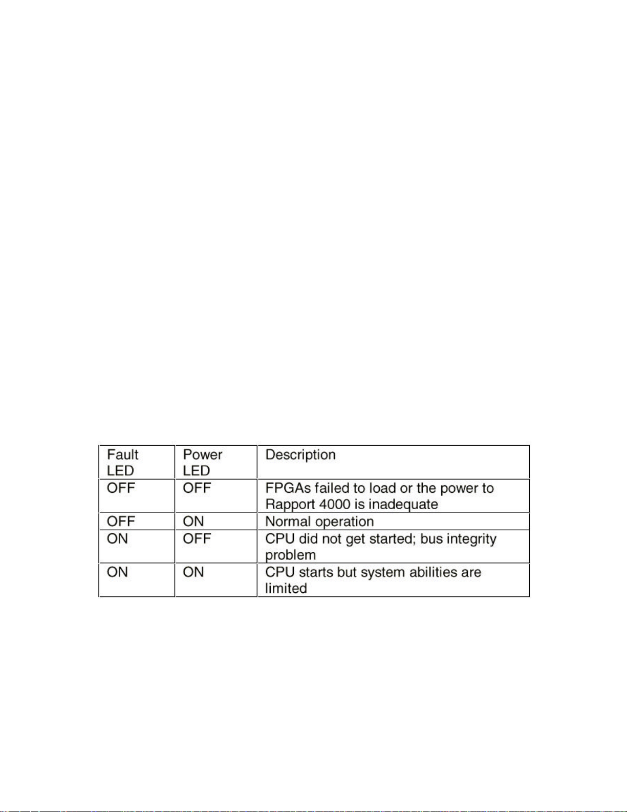
At power on, the green power and yellow fault LED’s are the only indicators in a known state of
power OFF and fault ON; all others are unknown and must be initialized. In this way, if the CPU
never gets started, the power will remain OFF and fault ON. The switch will need to be replaced.
If, as the diagnostics progress, the fault LED changes to ON and the port LED’s begin flashing,
this indicates a self-test failure.

10
Other LED indications:
Again, the switch will need to be replaced.
NOTE: When all memory and other internal tests successfully complete, the port LED’s are
turned OFF. The MEDIAswitch is now ready for operation. When a device establishes successful
communication with a port, that port LED will turn ON solidly, indicating that it is operational and
working successfully.
LED Indications
After all self-tests have completed, the port LEDs are turned OFF. The port LEDs then begin to
indicate Fibre Channel link states.
For a loop port, the port LED will begin blinking as it goes into loop arbitration. It will go to ON as
long as the loop is operational. An OFF LED indicates that it is resetting the hardware. Then it will
re-initialize the ports and start the process over again.
For a point-to-point connection, when the port is activated its LED will begin blinking (it may take
up to 10 seconds for some hardware devices to properly set up and begin communicating).
During this time and until the communication begins, the LED will blink.
A blinking Power LED indicates that a power supply has gone offline or that a brownout has
occurred. If there is a redundant power supply, it will have taken over. (Note: This LED will
continue to blink even if the offline power supply comes back online or until power is cycled.)
Check the Event Message log through SNMP to see if a message was logged. If this situation
happens repeatedly, it can mean that the power supply is failing.
A fast-blinking Fault LED (about two blinks per second) indicates that a system fan has stopped
running and the redundant fan has taken over.
Inhaltsverzeichnis
Andere Avid Technology Schalten Handbücher


