Bürkert 0911 Bedienungsanleitung

Operating Instructions
Bedienungsanleitung
Instructions de Service
Type 0911
2 stage controller
2-Punkt-Regler
2 Régulateur Ponctuel
Id. No. 788 263
788 264
788 265
788 266

We reserve the right to make technical changes without notice.
Technische Änderungen vorbehalten.
Sous resérve de modification techniques.
© 2004 - 2017 Bürkert Werke GmbH & Co. KG
Operating Instructions 1706/03_EU-ml_00804604

0911 - 1
english
1 GENERAL INFORMATION ........................................................................................................................ 2
1.1 Symbols ......................................................................................................................................................... 2
1.2 Safety notes ................................................................................................................................................ 2
1.3 Scope of delivery...................................................................................................................................... 3
1.4 Warranty provisions ............................................................................................................................... 3
2 SYSTEM DESCRIPTION ............................................................................................................................ 4
2.1 General description ................................................................................................................................. 4
2.2 Operation ...................................................................................................................................................... 4
2.3 Before the installation ............................................................................................................................. 7
2.4 Parameters .................................................................................................................................................. 8
2.5 Controlling the loads ............................................................................................................................. 11
3 TECHNICAL DATA ..................................................................................................................................... 12
4 ASSEMBLY, INSTALLATION AND COMMISSIONING .......................................................... 13
4.1 General information regarding the installation and operation ......................................... 13
4.2 Assembly .................................................................................................................................................... 13
4.3 Electrical connections .......................................................................................................................... 14
5 HOT-KEY FUNCTION ................................................................................................................................. 16
6 FACTORY SETTING .................................................................................................................................. 17
7 MAINTENANCE ............................................................................................................................................ 18
8 REPAIR WORK .............................................................................................................................................. 19
8.1 Faults............................................................................................................................................................. 19
8.2 Ordering table for basic unit/accessories ................................................................................ 20
2-STAGE CONTROLLER
TYPE 0911

2 - 0911
english
1 GENERAL INFORMATION
Please observe the notes in these operating instructions together with the
conditions of use and permitted data that are specified in the data sheets of
the 0911 controller, so that the device will function perfectly and will have a
long service life.
• Keep to the standard engineering rules when planning and operating the
device!
• Installation and maintenance work may only be carried out by specialist
personnel using the correct tools!
• Observe the current regulations on accident prevention and the safety
regulations for electrical devices during the operation and maintenance of
the device!
• Comply with the intended usage of the device.
• Only operate the device with its housing fitted.
• Before connecting the device, check that the power supply corresponds to
the values printed on the device.
• Check that the connections are correct before switching on the device.
• Observe the maximum load of the relay contacts (see technical data).
• Ensure that all sensors are installed with sufficient separation from voltage-
conducting lines. This will avoid incorrect temperature readings and will
protect the device from voltage interference at the sensor inputs.
• For applications in the industrial sector with critical environments, switch an
RC element in parallel (FT1).
• Always switch off the mains supply before carrying out manipulations on
the system.
• Take suitable measures to exclude unintended operation and damage by
unauthorised operation!
1.1 Symbols
1.2 Safety notes
The following symbols are used in these operating instructions:
marks a work step that must be carried out.
ATTENTION! indicates information which, if ignored, could lead to a risk to
your health or to the functionality of the device.
NOTE indicates important additional information,
tips and recommendations.

0911 - 3
english
1.3 Scope of delivery
Immediately after receiving the delivery, ensure that the contents agree with
the scope of the delivery. This includes:
• 1 Type 0911 controller
• 1 set of operating instructions (where required, on a data carrier)
• 1 front seal
• 2 Mounting clamps
1.4 Warranty provisions
Bürkert provideds a guarantee of one year on the correct functioning of the
controller, under the precondition that the device is employed for its intended
use and under compliance with the specified conditions for use.
If the functions of the device are not in order, the respective device will be
repaired free of charge or will be replaced.
ATTENTION! The warranty only covers the the controller and its compo-
nents, but does not cover consequential damage of any kind
that could arise from the failure or malfunctioning of the device.
In case of discrepancy, please contact our Customer centre immediately:
Bürkert Steuer- und Regelungstechnik
Service-Abteilung
Chr.-Bürkert-Str. 13-17
D-76453 Ingelfingen
Tel. : 07940-10111
or your Bürkert Sales Centre.
• Please observe the prescribed environmental conditions with regard to
dampness and temperature limits. Malfunctions cannot be excluded if these
conditions are not complied with.
• Call in your authorised Bürket sales centre in case of doubt or faulty
functioning.
In the case of the non-observance of these notes or of unauthorised
manipulation of the device, we will accept no liability, and the guarantee on the
device and its accessories will become void!
4 - 0911
english
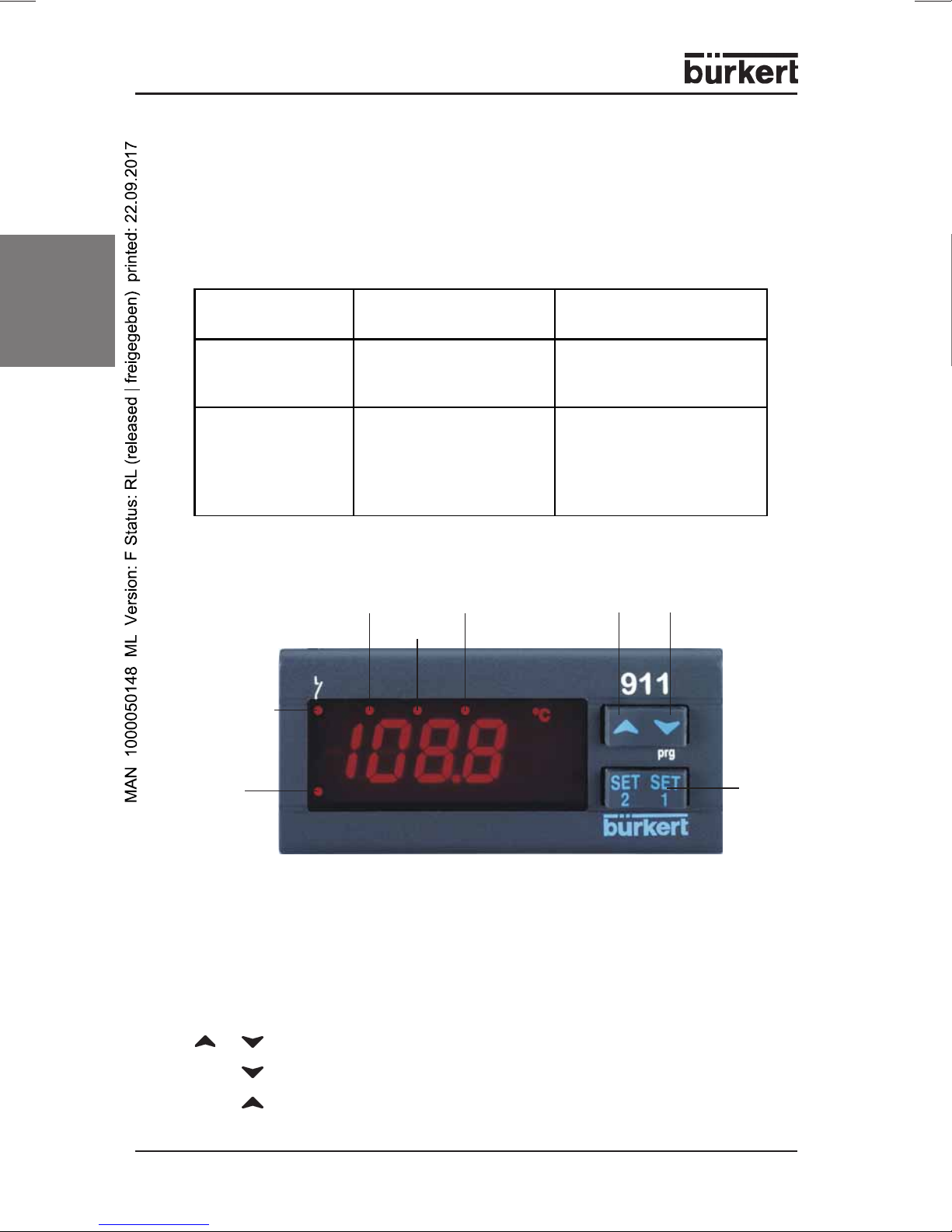
2-point controller, 74 x 32 mm, with predefinable control function (e.g., heating/
cooling or moisten/dehumidify)
The following models are available:
2.1 General description
2 SYSTEM DESCRIPTION
2.2 Operation
BUTTONS
SET Display of the set-value,
Changing and confirming a default during the programming phase
up-
wards
down-
wards
LED 2
SET
button
ES LED
LED1
Type Configurable Input Parameter UDM
(Defined by display unit)
TU
Temperature
controller
PTC, NTC, Pt100
Thermoelements J, K, S
UDM = °C
UDM = °F
AU
Control device with
current / voltage
input
4 ... 20 mA
0 ... 1 V
0 ... 10 V
0 = °C; 1 = °F
2 = % RH
3 = bar
4 = PSI
5 = without units
BUTTON COMBINATIONS
Locking and unlocking the keypad
SET+ Selecting the programming level
SET+ Return to the room temperature display
+
Alarm
LED
Output 1
0911 - 5
english
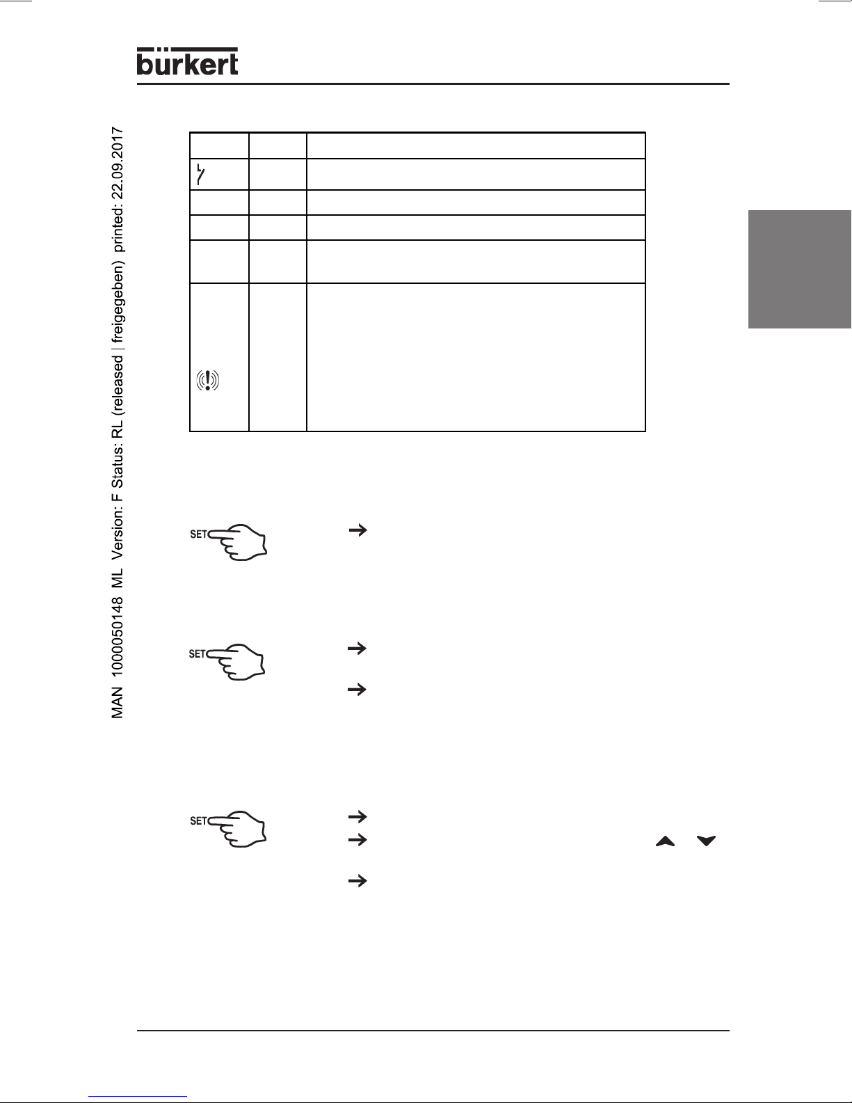
LED Mode Meaning
on Output active
LED1 blinks Programming level (blinks together with LED2)
LED2 blinks Programming level (blinks together with LED1)
E.S. on Energy-saving mode (second set-value) has
been activated by the digital input
Alarm
LED on
- Signals an Alarm state
- If you are in the lower programming level
"Pr2", which can only be accessed using
a password, the lighting up of the Alarm LED
signals that the displayed parameters can
also be accessed in the first level Pr1
(without password).
LED MESSAGES
SET-VALUE DISPLAYS
Briefly press the SET button once. The set-value
display appears in the display.
Briefly press the SET button again, or wait 5
seconds in order to display the room temperature.
SWITCH DEVICE ON/OFF
Hold the SET button down for at least 4 sec
(only for parameter OnF = yes).
CHANGE THE SET VALUE
Hold the SET button down for 2 seconds.
Change the set-value within 10 s with the or
buttons.
You can save the new set-value by briefly pressing
the SET button or by waiting 10 seconds.

6 - 0911
english
ENTER PROGRAMMING LEVEL
Hold the SET + buttons down for at least 3
seconds
Select with Pr2 and then confirm with the SET
button.
Enter the password 321 and then confirm with the
SET button.
Enter the „3“ and then 1x SET button
Enter the „2“, and then 1x the SET button
Enter the „1“, and then 1x the SET button
You are now in the Parameter List.
USER LEVEL PR1
Press down the SET + buttons for 3 seconds.
PR1 contains all the parameters accessible to the
user. The device shows the first parameter that is
available in the user level.
SERVICE LEVEL PR2 (PASSWORD 321)
See:
Accessing the programming level.
ADDING/REMOVING PARAMETERS INTHE USER LEVEL „PR1“
Accessing the programming level
The status can be changed with the SET +
buttons.
If a parameter is not visible in the PR1 level, this will
be indicated by an LED point.
CHANGINGTHE DEFAULT PARAMETERS
Enter a desired value with SET + or .
Then confirm with the SET button.
Enter a desired parameter with or .

0911 - 7
english
LOCKING AND UNLOCKINGTHE KEYPAD
Hold down the buttons and for at least 3
seconds. The POF message appears on the
display.
The keyboard is locked. You can only view the
set-value and the minimum and maximum
temperature. The POF message also appears if you
hold down a button for longer than 3 s.
The keyboard will be unlocked if you hold down
the buttons and for 3 s. POn appears in the
display for a few seconds.
NOTE All parameter values can be seen by repeatedly pressing the
SET buttons.
2.3 Before the installation
PREDEFINE THE SENSOR TYPE
Hold down the SET + button for at least 3
seconds.
Select the parameter Pbc (sensor type) and then
confirm with the SET button to see the current
default.
Type TU (temperature controller):
J = Thermoelement J; Pt = Pt100;
C = Thermoelement K; Ptc = PTC;
S = Thermoelement S; ntc = NTC
Type AU
(control devices with voltage/current input):
cur = 4...20 mA; 0-1 = 0...1 V; 10 = 0...10 V
Confirm the default with the SET button.
Briefly switch off the power to the device.
The configurable input type is noted on the controller
label. Please enter this input type if it does not
corresponds to the connected sensor type.

8 - 0911
english
2.4 Parameters
Control
Hy1
Hysteresis 1
Switch hysteresis of Set-value 1 with
positive or negative values. The default
range is dependent on the input type.
The parameter may not be entered as
zero.
LS1
Lowest set-value setting
Set-value limits for operator
US1
Highest set-value setting
Set-value limits for operator
S1C
control effect
in = inverse (heating, humidification)
dir = direct (cooling, dehumidification)
AC
Minimum switch duration
0...250 sec relay switch-off duration
on
Minimum switch-on period
0...250 sec relay switch-on period
ono
Minimum delay
0...120 min; minimum delay between two
activations of the control relay.
Alarms
ALC
Configuration
rE = relative to the set-value (in Kelvin)
Temperature alarm
Ab = absolute values (in °C)
ALL
Low temperature alarm
If SET - ALL is undershot,
a low temperature alarm will be triggered
after the delay time ALd.
ALU
Over-temperature alarm
If SET + ALU exceeded, a high
temperature alarm will be triggered after
delay time ALd.
ALd
Alarm delay
0...999 min; Minimum time in which the
at
temperature
conditions for an alarm situation
Overshoot/Undershoot
must be present.
Sensor Lower limit Upper limit
NTC -40°C 110°C
PTC -50°C 150°C
Pt100 -200°C 600°C
TcK 0°C 1300°C
TcJ 0°C 600°C
TcS 0°C 1400°C
MEASUREMENT LIMITS FOR THE SENSOR TYPES
Andere Handbücher für 0911
1
Inhaltsverzeichnis
Sprachen:
Andere Bürkert Controller Handbücher

Bürkert
Bürkert 8311 Bedienungsanleitung

Bürkert
Bürkert Type 8605 Bedienungsanleitung

Bürkert
Bürkert eCONTROL 8611 Bedienungsanleitung

Bürkert
Bürkert 2012 Bedienungsanleitung

Bürkert
Bürkert 8692 Bedienungsanleitung

Bürkert
Bürkert 8619 multiCELL WM AC Bedienungsanleitung

Bürkert
Bürkert TopControl ON/OFF Bedienungsanleitung

Bürkert
Bürkert 8690 Bedienungsanleitung

Bürkert
Bürkert 8691 Bedienungsanleitung


