
Badger Power Electronics BPE-HI-3.6K Bedienungsanleitung

HYBRID INVERTER
SOLAR/STORAGE/WIND/
BACK-UP GENERATOR
USER MANUAL
BPE-HI-3.6K & BPE-HI-5K

Contents Contents
………………………………………………
………………………………………………
……………………………………………………………
……………………………………………………………
……………………………………………………
01
01-04
27-29
33-34
04-16
17
18-27
Contents
1. Safety Introduction
2. Product instructions
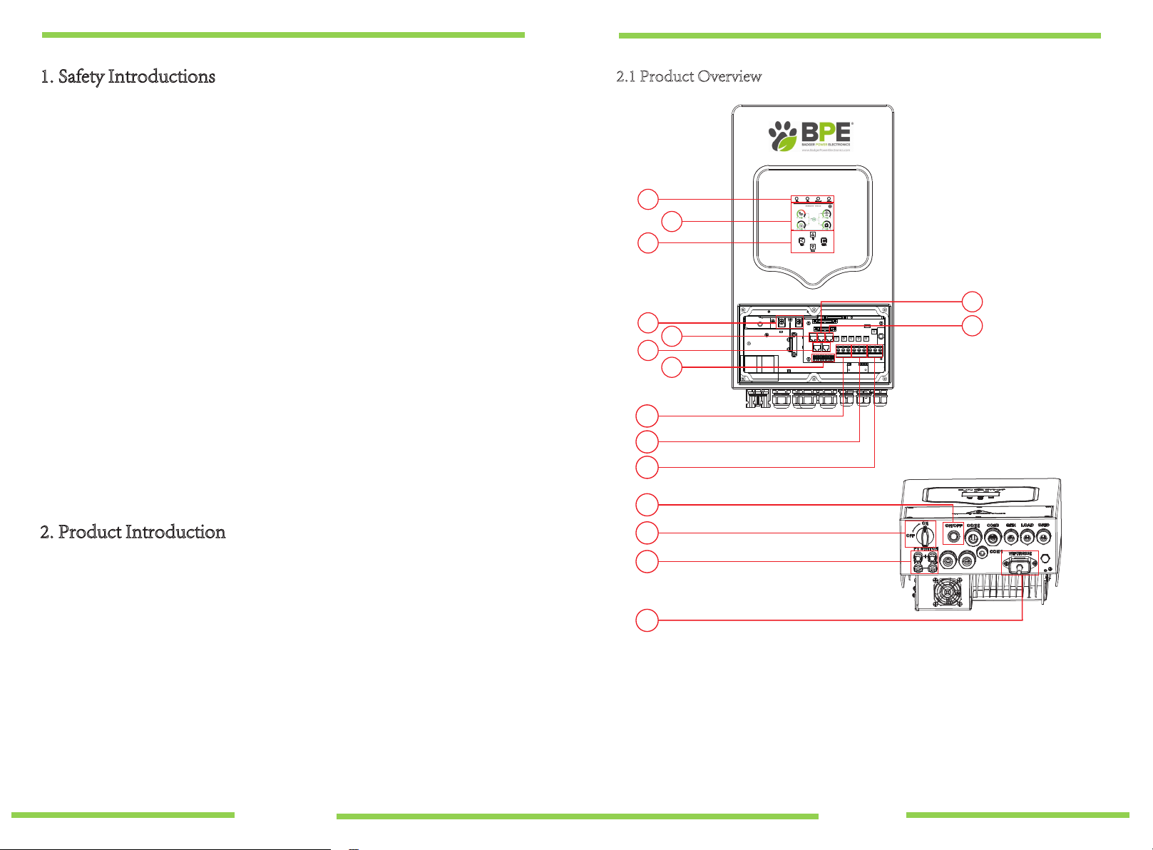
2.1 Product Overview
2.2 Product Features
2.3 Basic System Architecture
3. Installation
3.1 Parts list
3.2 Mounting instructions
3.3 Battery connection
3.4 AC Input/Output Connection
3.5 PV Connection
3.6 CT Connection
3.7 Earth Connection(mandatory)
3.8 WIFI Connection
3.9 Wiring System for Inverter
3.10 Single phase parallel connection diagram
3.11Three phase Parallel Inverter
4. OPERATION
4.1 Power ON/OFF
4.2 Operation and Display Panel
5. LCD Display Icons
5.1 Main Screen
5.2 Solar Power Curve
5.3 Curve Page-Solar & Load & Grid
5.4 System Setup Menu
5.5 Basic Setup Menu
5.6 Battery Setup Menu
5.7 System Work Mode Setup Menu
29-32
30-31
5.8 Grid Setup Menu
5.9 Wind Turbine Connection
5.10 Generator Port Use Setup Menu
5.11 Advanced Function Setup Menu
5.12 Smart Load
Mode ……………………………………………………………………
Fault information and processing …………………………………
Limitation of Liability …………………………………………………
Datasheet ………………………………………………………………
WIFI/GPRS dongle installation and Solarman remote
monitoring setup
Programming Quick Start
Guide BPE Hybrid Inverter
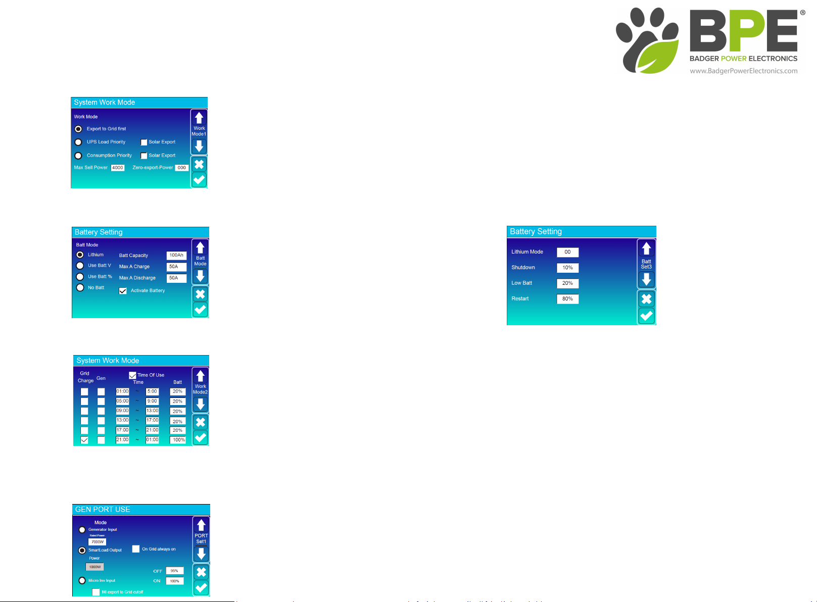
System Work Mode
Battery Settings - Time Of Use
'EWKZdh^
Home Screen > System Work Mode
Export to Grid First - All excess power will be exported to the grid.
UPS Load Priority - The hybrid inverter will only power the loads connected to the load port and will not produce more power than the connected loads require.
This mode by default will export ZERO to the grid unless "Solar Export" is ticked.
Consumption Priority - The hybrid inverter will push power to the whole home load (this mode requires the included CT clamp) see page 13 of the user manual.
This mode by default will export ZERO to the grid unless "Solar Export" is ticked. WƌĞƐƐƚŚĞƚŝĐŬĂƚƚŚĞďŽƚƚŽŵŽĨƚŚĞƐĐƌĞĞŶƚŽƐĂǀĞLJŽƵƌƐĞůĞĐƚŝŽŶ
Home Screen > Battery Settings
Home Screen > System Work Mode > Arrow Down > Time Of Use Settings
This screen will allow you to set the parameters for discharging the battery
to the load and also charging the battery from the grid or a generator.
Once you have completed the above step and activated the Lithium battery
you will need to programme the time of use settings, selecting Time Of Use
will allow the battery to be discharged to the load until a user set SOC % is reached during the pre-set 6 time periods. You can also select whether you
want to charge the battery from the Grid or a Generator. For example, on the image to the left we have programmed the time of use to discharge the battery to the load
between 01.00am - 21.00pm until the battery SOC reaches 20% and then for the grid to fully charge the battery between 21.00pm and 01.00am. WƌĞƐƐƚŚĞƚŝĐŬĂƚƚŚĞ
ďŽƚƚŽŵŽĨƚŚĞƐĐƌĞĞŶƚŽƐĂǀĞLJŽƵƌƐĞůĞĐƚŝŽŶ
Home Screen > Gen Port Use
dŚĞ'EWKZdŝƐĂŵƵůƚŝĨƵŶĐƚŝŽŶŝŶƉƵƚŽƵƚƉƵƚŽĨĨĞƌŝŶŐϯĚŝĨĨĞƌĞŶƚĨƵŶĐƚŝŽŶƐ zŽƵĐĂŶƐĞůĞĐƚŽŶĞŽĨƚŚĞĨŽůůŽǁŝŶŐ
'ĞŶĞƌĂƚŽƌ/ŶƉƵƚ
^ŵĂƌƚ>ŽĂĚKƵƚƉƵƚͲdŚŝƐŵŽĚĞƵƚŝůŝƐĞƐƚŚĞ'ĞŶŝŶƉƵƚĐŽŶŶĞĐƚŝŽŶĂƐĂ^ŵĂƌƚ>ŽĂĚŽƵƚƉƵƚǁŚŝĐŚŽŶůLJƌĞĐĞŝǀĞƐƉŽǁĞƌǁŚĞŶƚŚĞƌĞŝƐĞdžĐĞƐƐƉŽǁĞƌŐĞŶĞƌĂƚŝŽŶĂŶĚƚŚĞďĂƚƚĞƌLJ
^KŝƐĂďŽǀĞĂƵƐĞƌƉƌŽŐƌĂŵŵĂďůĞƚŚƌĞƐŚŽůĚ dŚĞ'ĞŶŝŶƉƵƚƉŽƌƚŝŶƚŚĞƵƐĞƌĂƌĞĂŽĨƚŚĞƐLJƐƚĞŵďĞĐŽŵĞƐĂŶŽƵƚƉƵƚƚŽŚŝŐŚƉŽǁĞƌůŽĂĚƐƐƵĐŚĂƐĂǁĂƚĞƌŚĞĂƚĞƌŝƌƌŝŐĂƚŝŽŶ
ƉƵŵƉĂĐƵŶŝƚŽƌĂŶLJŽƚŚĞƌĚĞǀŝĐĞ
DŝĐƌŽ/Ŷǀ/ŶƉƵƚͲdŚŝƐǁŝůůĂůůŽǁĐŽƵƉůŝŶŐŽĨDŝĐƌŽ/ŶǀĞƌƚĞƌƐŽƌŐƌŝĚƚŝĞĚŝŶǀĞƌƚĞƌƐŝŶĂĚĚŝƚŝŽŶƚŽƚŚĞƌĂƚĞĚŝŶƉƵƚŽĨƚŚĞŝŶǀĞƌƚĞƌ
Press the tick at the bottom of the screen to save your selection.
Battery Settings
Installing the hybrid inverter with a BPE 4.8kWh battery with integrated BMS
Select "Lithium"
Set the battery parameters as in the image
Select "Activate Battery"
Press the tick at the bottom of the screen to save your selection.
When using Time Of Use function below you will first need to change the
default battery low % (page 3 in the battery settings LCD screen) to what you
would like the minimum SOC that the battery will discharge too, anything
below 20% can affect the life expectancy of the battery.
Press the tick at the bottom of the screen to save your selection.
1. Safety Introductions 2.1 Product Overview
·This chapter contains important safety and operating instructions. Read and keep this
manual for future reference.
·Before using the inverter, please read the instructions and warning signs of the battery
and corresponding sections in the instruction manual.
·Do not disassemble the inverter. If you require maintenance or repair, please take it to a
professional service center.
·Incorrect reassembly may result in electric shock or fire.
·To reduce the risk of electric shock, disconnect all wires before attempting any
maintenance or cleaning. Turning off the unit will not reduce this risk.
·Caution: Only qualified personnel can install this device with a battery.
·
·
·
Never charge a frozen battery.
For optimum operation of this inverter, please follow the required specification to
select appropriate cable size, failure to do so will damage the inverter.
Be very cautious when working with metal tools on or around batteries, dropping a
tool may cause a spark or short circuit in the battery or other electrical parts, and
even cause an explosion.
·Please follow the installation procedure when you want to disconnect AC or DC
terminals. Please refer to "Installation" section of this manual for details.
·Grounding instructions - this inverter should be connected to a permanent grounded
wiring system. Be sure to comply with local requirements and regulations whilst
installing this inverter.
·Never cause AC output and DC input to be short circuited. Do not connect to the
mains when DC input short circuits.
2. Product Introduction
This is a multi-functional inverter, combining functions of a PV/WIND inverter, battery
charger and generator back-up to offer uninterruptible power support for both on-grid and
off-grid applications. The comprehensive LCD touchscreen display offers users
configurable and easily accessible features such as battery charging, AC/solar charging, and
acceptable input voltage based on different applications.
1: Inverter LED Indicators
2: Touchscreen LCD display
3: Function Buttons
4: Battery input connectors
5: RS485 Port
6: CAN Port
7: DRMs Port
8: Parallel port
9: Function Port
10: Generator input 16: WiFi Interface
11: Load
12: Grid
13: Power on/off button
14: DC Switch
15: PV input with two MPPT
1
2
5
9
10
11
12
14
15
16
13
7
6
3
4
8
- 01 - - 02 -

2.2 Product Features
· -230V Single phase Pure sine wave inverter.
· - Self-consumption and feed-in to the grid.
· - Auto restart while AC is recovering.
· - Programmable supply priority for battery or grid.
· - Programmable multiple operation modes: On-grid, off-grid and UPS.
· - Configurable battery charging current/voltage based on applications via LCD display.
· - Configurable AC/Solar/Generator Charger priority via LCD display.
· - Compatible with mains voltage or generator power.
· - Overload/over temperature/short circuit protection.
· - Smart battery charger design for optimised battery performance.
· - With limit function, prevent excess power overflow to the grid.
· - Supports WIFI/GPRS monitoring and built-in 2 strings of MPP trackers.
· -Smart programmable three stage MPPT charging for optimised battery performance.
· -Time of use function.
· -Smart Load Function.
· -Parallel function On-Grid & Off-Grid.
2.3 Basic System Architecture
The following illustration shows basic application of this inverter.
It also includes the following devices to show a Complete running system.
- Generator or Utility
-Wind Controller and Wind Turbine (sold separately)
- PV modules
Consult with your system integrator for other possible system architectures depending on your
requirements.
This inverter can power all kinds of appliances in the home or office environment, including
motor type appliances such as a refrigerator and air conditioner.
3. Installation
3.1 Parts List
Please check the equipment before installation. Please make sure nothing is damaged in the
package. You should have received the items below.
No Description Qty
1
2
3
4
5
BPE-HI-3.6/5K hybrid inverter
Stainless steel mounting screws M6*12
Stainless steel expansion bolts M8*80
User manual
Wi-Fi plug
1
2
4
1
1
123
6 7 8 9
4 5
- 03 - - 04 -

Considering the following points before selecting where to install:
· Not in direct sunlight.
· Not in areas where highly flammable materials are stored.
· Not in potential explosive areas.
· Not in the cool air directly.
· Not near a television antenna or antenna cable.
· Not higher than an altitude of 2000 meters above sea level.
· Not in an environment of precipitation or humidity (>95%)
Please AVOID direct sunlight, rain exposure, snow laying up during installation and
operation. Before connecting all wires, please remove the front cover by removing
the screws as shown below:
· The ambient temperature should be between -25~60℃ to ensure optimal operation.
· Be sure to keep other objects and surfaces at a distance as shown in the diagram to
guarantee sufficient heat dissipation and to have enough space for accessing cables.
· Please select a vertical wall with load-bearing capacity for installation, suitable for
installation on concrete or other non-flammable surfaces, installation is shown below.
· Install this inverter at eye level in order to allow the LCD display to be read at all times.
Chart 3-1 Parts List
3.2 Mounting instructions
Installation Precaution
This Hybrid inverter is designed for outdoor use (IP65). Please make sure
the installation site meets the below criteria:
6
7
8
9
Current transformer CT (Optional)
Battery sensor
L-type Hexagon wrench
Wall mounting bracket
1
1
1
1≥500mm
≥500mm
For proper air circulation to dissipate heat, allow a clearance of approx. 50cm to the side,
approx. 50cm above and below the unit and 100cm to the front.
Mounting the inverter
The inverter should be installed vertically, as shown, installation procedure shown below:
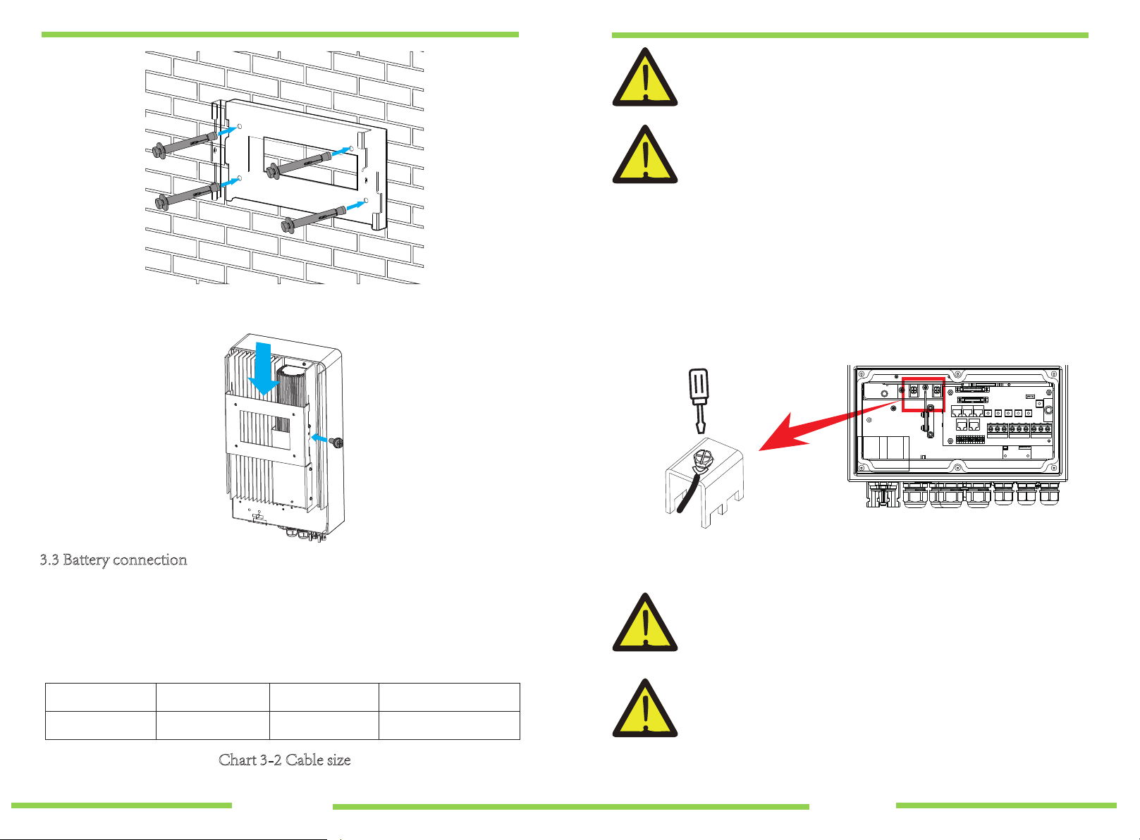
1. Position the bolts on the appropriate wall according to the bolt positions on the
mounting shelves and mark the holes. The installation site must be suitable for
expansion bolt installation.
2. Ensure that the position of the installation holes on the wall (A, B, C, D) are the
same position of the install plate, and the mounting level is correct.
3. Hang the inverter to the top of the mounting rack and then use the M4 screw in the
accessory pack to lock E and F to ensure that the inverter does not move.
- 05 - - 06 -
xxx
x
xx
3.3 Battery connection
Chart 3-2 Cable size
For safe operation and compliance, a separate DC over-current protector or disconnect
device is required between the battery and the inverter. In some applications, switching
devices may not be required but over-current protectors are still required. Refer to the
typical amperage in the table below for the required fuse or circuit breaker size.
All wiring must be performed by a professional.
Connecting the battery with a suitable cable is important for safe and
efficient operation of the system. To reduce the risk of injury, refer to
Chart 3-2 for the recommended cable specification.
Please follow the below steps to implement battery connection:
1. Please choose a suitable battery cable with the correct connector which can fit into the
battery terminals.
2. Use a suitable screwdriver to unscrew the bolts and fit the battery connectors, then fasten
the bolt with the screwdriver, making sure the bolts are tightened with a torque of 5.2
N.M in clockwise direction.
3. Make sure the polarity at both the battery and inverter is correctly connected.
Model
3.6/5KW
Wire Size
8AWG
Cable(mm )
2
8.4
Torque value(max)
5.2Nm
Installation must be performed with care.
Before making the final DC connection or closing the DC breaker/
disconnect, make sure the positive (+) is connected to positive (+)
and negative (-) is connected to negative (-). Reverse polarity
connection on the battery will damage the inverter.
Inverter hanging plate installation
- 07 - - 08 -
+-

3.3.2 Battery temperature connection 3.4 AC Input/Output Connection
·Before connecting to AC input power source, please install a separate AC
breaker between the inverter and AC input power source. This will ensure the
inverter can be securely disconnected during maintenance and fully protected
from over current of AC input. The recommended AC breaker is 25A for 3.6kW and
32A for 5kW.
·There are three terminal blocks with "Grid" "Load" and "GEN" markings. Please
do not misconnect the input and output connectors.
1. Before making the AC input/output connection, be sure to open the DC
protector or disconnecter first.
2. Remove 10mm of the insulation sleeve, unscrew the bolts, insert the AC input
cables according to polarities indicated on the terminal block and tighten the
terminal screws. Making sure the connection is complete.
All wiring must be performed by a qualified person. It is very
important for system safety and efficient operation to use the
appropriate cable for AC input connection. To reduce risk of injury,
please use the recommended cable as below.
Please follow below steps to implement AC input/output connection:
Chart 3-3 Recommended Size for AC wires
3.6KW
Model
5KW
12AWG
Gauge
10AWG
4
6
1.2Nm
1.2Nm
Cable(mm )
2Torque value
NGrid
Load
GEN PORT
LPE
1 2
Temp. CT
- 09 - - 10 -

3. Then, insert AC output wires according to polarities indicated on the terminal block and
tighten the terminals. Be sure to connect the corresponding N wires and PE wires to
related terminals.
4. Make sure the wires are securely connected.
3.5.1 PV Module Selection:
When selecting PV modules, please be sure to consider the below parameters:
1) Open circuit Voltage (Voc) of PV modules doesn't exceed max. PV array open
circuit voltage of inverter.
2) Open circuit Voltage (Voc) of PV modules should be higher than min. start voltage.
3.5 PV Connection
Before connecting to PV modules, please install a separate DC circuit breaker between
the inverter and PV modules. It is very important for system safety and efficient
operation to use the appropriate cable for PV module connection. To reduce risk of
injury, please use the recommended cable size as below.
Be sure that the AC power source is disconnected before attempting to wire
it to the unit.
To avoid malfunction, do not connect any PV modules with possible
current leakage to the inverter. For example, grounded PV modules will
cause current leakage to the inverter. When using PV modules, please be
sure there is NO grounding.
It is requested to use a PV junction box with surge protection.
Otherwise, it will damage the inverter when lightning occurs on PV
modules.
Chart 3-5
Chart 3-2 Cable size
Model
3.6/5KW
Wire Size
1X12AWG
Cable(mm )
2
4
PV Input Voltage (V)
Inverter Model 3.6KW 5KW
370V(100V~500V)
125Vdc-425VdcPV Array MPPT Voltage Range
No. of MPP Trackers
No. of Strings per MPP Tracker
2
1+1
- 11 - - 12 -

3.6 CT Connection 3.9 Wiring System for Inverter
3.7 Earth Connection(mandatory)
Ground cable shall be connected to ground plate on grid side to prevent electric shock
if the original protective conductor fails.
3.8 WIFI Connection
For the configuration of the Wi-Fi Plug, please refer to illustrations of the Wi-Fi
Plug at the end of this user manual.
Battery
Solar
Breaker
CAN
Breaker
Breaker
Earth-BAR
34CT
Generator
Microinverter
Smart Load
L
N
PE
Breaker
or
or
Loads
Loads
Ground
N L PE
White wire
Inverter
3 4 Black wire
Grid L
N
CT
34
- 13 - - 14 -
CT arrow points away from grid
+-
Dieses Handbuch passt für folgende Modelle
1
Inhaltsverzeichnis
Andere Badger Power Electronics Wechselrichter Handbücher


