CONNECTORBOARD
Let’s start with the connector board PCB. Before you start soldering, take your time and find all the
resistorsvaluesusingamultimeter (oryoucancheckthecolorcodesifyouareseasonedenough).
2
Now insert and solder 21 resistors (7x 10k, 14x 1k). Then snip the leads as close to the PCB as you
can(besuretomakethissteponallremainingleadsinthecourseofthisguide).
Turn around the PCB and insert seven
transistors (2N3904). Watch out for
orientation! Flat side of transistors must
match the outline drawn on the PCB. You may
also want to push the leads in the upper part
closer to each other to insert the transistors
closer to the PCB (although they should not
beflatwiththePCB).
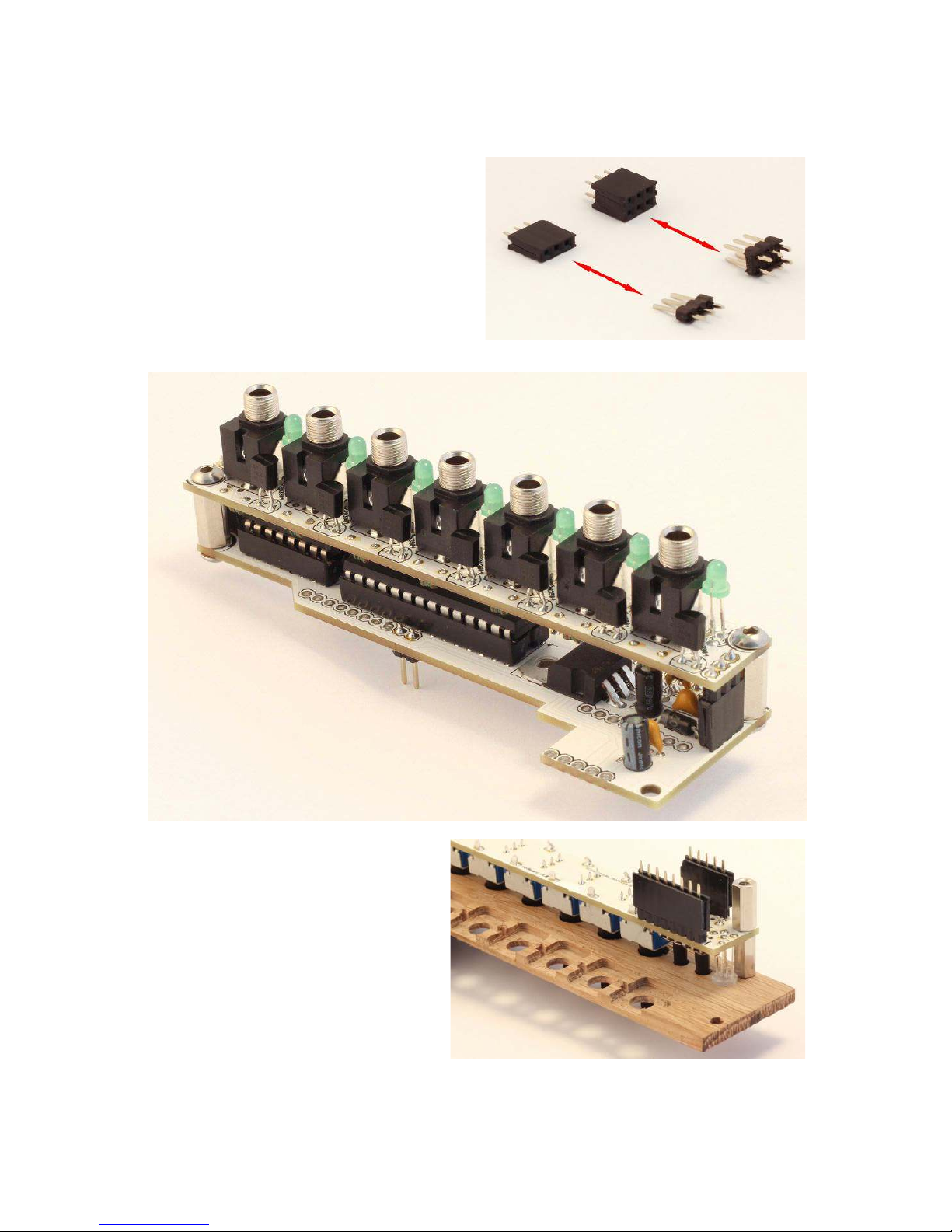
Next insert seven jacks and seven green LEDs. Be careful to put the longer lead of LEDs into the
plus (+) hole. Jacks must sit flat on the board, otherwise they will not come easy through the front
panel.Donotsolderanythingyet.
2https://learn.sparkfun.com/tutorials/howtouseamultimeter/measuringresistance
3