9
Medical Gas Central Alarm - Medipoint 125 Digital Alarm
4233500107.03
1.4 Visual displays
Colour LCD touch screen display provides the visual
display detailed in paragraph 1.1, gure 1. All ashing
displaysashatarateof0.4secondson,0.4secondso
inaccordancewithISO7396-1andHTM02-01/HTM2022.
1.5 Audible warning
Theaudiblewarningspeakerttedtotheinsideofthe
alarmpaneldoorandconnectedtotheprocessorPCBby
plugandsocket(seegure2)operatessimultaneously
with any HIGH PRESSURE, LOW PRESSURE or SYSTEM
ALARMindication. The audiblewarning may bemuted
bypressingtheMUTEswitch(seegure1).Iffollowing
a mute condition another alarm condition occurs, the
audible warning will operate simultaneously with the
indication.Followingamuteconditionandacontinuing
alarmindication,theaudiblewarningwillresoundafter
15minutesinaccordancewithHTM02-01/HTM2022and
C11. When the audible re-sounds further operation of
theMUTEswitchisnecessarytocanceltheaudible.
If following an alarm condition no action is taken to
MUTEtheaudible,theaudiblewarningwillautomatically
switchowhenthealarmconditionrevertstoNORMAL.
The audible tone consists of a modulation between
twotones(F1andF2).F1=440HzandF2=880Hz.The
modulationrateis4HzinaccordancewithHTM02-01/
HTM2022andC11.
1.6 Printed circuit boards
Twoprintedcircuitboardsarettedinsidemedicalgas
centralalarm;apowersupplyPCBandaprocessorPCB.
AllcomponentsaremountedonthesePCB’s,whichare
interconnected by means of a multi-way ribbon cable
and polarised connector (see gure 2 & 3). The area
central alarm internal electrical installation complies
with all relevant British Standard specications, IET
wiringregulationsandcurrentUKlegislation.
1.6.1 Processorprintedcircuitboard
The Processor PCB is retained inside the alarm panel
frontcoverwithfourretainingstuds.ThisPCBissupplied
witharibboncableforconnectiontothepowersupply
PCB,andconnectorforlinkingtothecontrolfascia,LCD
touchscreenandinternalspeaker(seegure6).
Theblockindicatorisaplug-incomponentenablingeasy
replacementorsubsequentupdatingoftheinstallation.
Theribboncableispermanentlyattachedtotherearface
ofthelightdisplayPCBandenablesinterconnectionof
circuitswiththepowersupplyPCB.Theaudiblewarning
speaker is connected by plug and socket to the light
display PCB and locates within the alarm panel front
coverwheninstalled.
1.6.2Displaypositions
Toprovideanaestheticdisplayandmaintainconsistency
inaccordancewithrecognisedandestablishedmedical
gasservicesequencing,itisrecommendedthatdisplays
arepositionedinthefollowingsequenceoneachalarm
panelcommencingwithfromlefttoright(seegure7
example):-
Gas Type Legend
MedicalOxygen O2
NitrousOxide N2O
Oxygen/NitrousOxideMix(50/50) O2/N2O
MedicalAir400kPa Air
MedicalAir700kPa Air-800
MedicalVacuum Vacuum
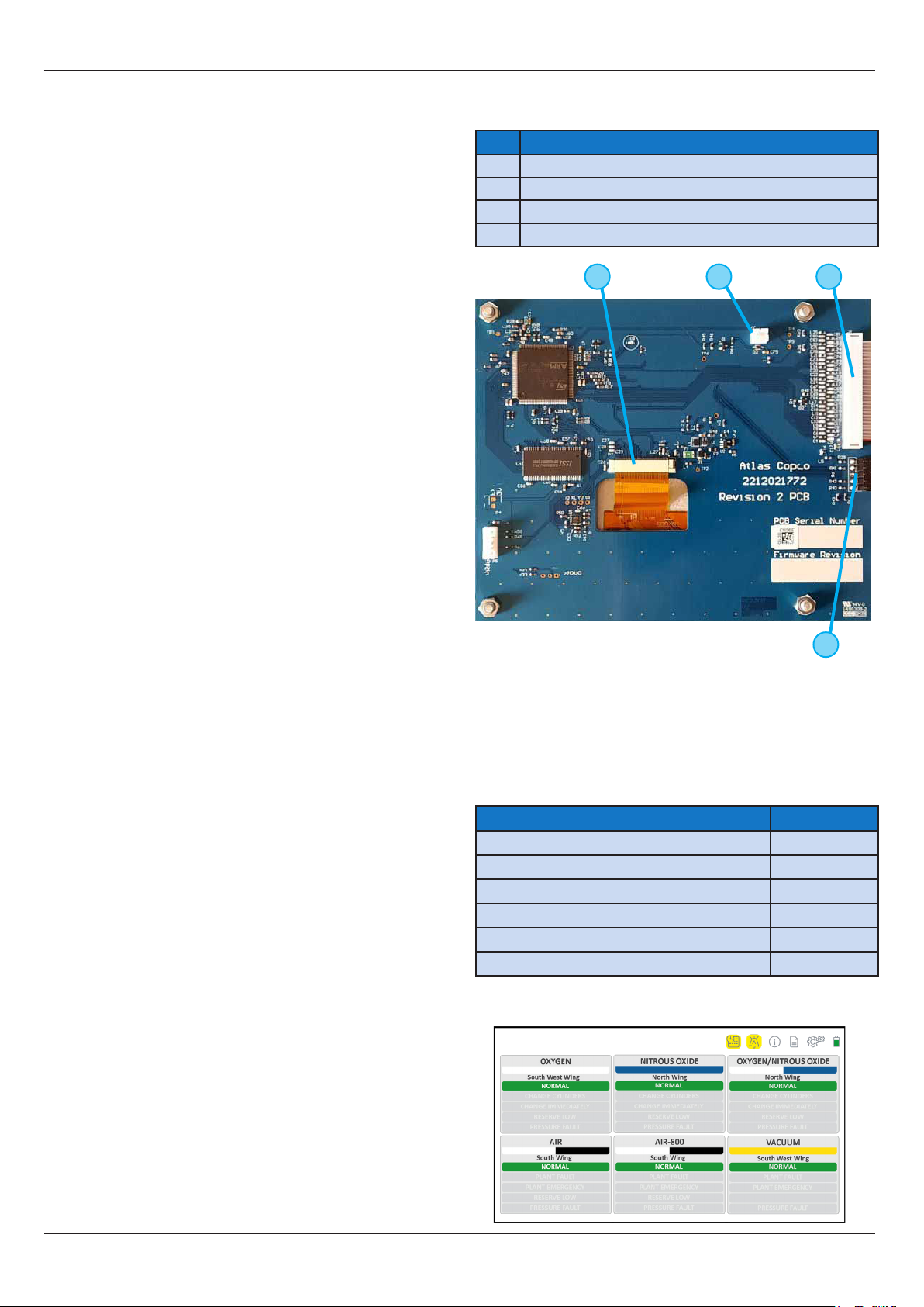
Figure 6 - Processor PCB
1
2
3 4
Medipoint125consistsof:-
No. Description
1ProcesstopowersupplyPCBribboncable
2Controlfasciaconnector
3LCDtouchscreenconnector
4Audiblespeakerconnector
Figure 7 - Gas source layout example.