
belavi 23700-23 Bedienungsanleitung
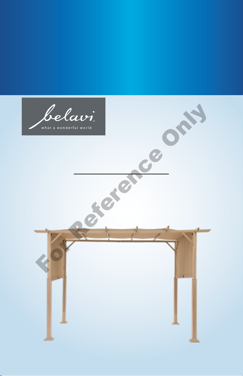
User Manual
________________
Manual
del usuario
PERGOLA
English.... Page 3
Español.... Página 25
PÉRGOLA
For Reference Only
Getting Started .................................. 3
Warnings & Cautions .......................... 4
Pack Contents .................................... 5
Parts List ............................................. 6
Hardware List .................................... 7
Assembly Instructions ....................... 8
Warranty ............................................ 22
Contents •Índice
Para comenzar .................................. 25
Advertencias y precauciones ............ 26
Contenido de la caja/piezas .............. 27
Lista de piezas ................................... 28
Lista de herraje .................................. 29
Instrucciones de ensamblaje ............ 30
Garantía ............................................. 44
For Reference Only
3
Getting Started
Ensure all parts packaged in carton match the parts list.
Remove all protective materials and place parts on a
non-abrasive surface to avoid scratching. If any parts are
missing or damaged, DO NOT attempt to assemble. Please
contact our customer service center (Monday-Friday
9:00am – 5:00pm EST) at 1-800-599-8898.
Caution
Read all the instructions before assembly. Failure to
comply with instructions may result in faulty assembly and
potential injury! Assemble product on a soft, non-abrasive
surface such as a carpet or cardboard to avoid damaging
the item. Seek assistance to assemble bulky or heavy
items. After final alignment, make sure all bolts and nuts
are securely tightened with screw covers pressed in place.
We do not recommend securing this structure to a patio
deck or concrete surface, nor can we advise on how to
do so.
Cleaning & Maintenance
Wash canopy top with a mild solution of soap and water;
rinse thoroughly. Dry completely.
Getting Started
For Reference Only
WARNING
KEEP ALL FLAME AND HEAT SOURCES AWAY FROM THIS TENT
FABRIC. This tent is made with fabric that meets CPAI-84 specicaons
for ame resistance. It is not re proof. The fabric will burn if le in
connuous contact with any ame source.
Warnings & Cautions
1. Some sections require working overhead and lifting components. Beams
can be heavy and awkward to lift into place by yourself.
2. Ask others to lend a hand. We recommend having four people to help
in the assembly of your pergola. Having others to help in the building
process will result in faster installation.
3. Use appropriate safety measures when working on ladders. Make sure
any ladders you’re using are sturdy and safe. Follow manufacturer safety
instructions when using ladders.
4. Keep a clean, uncluttered work space.
5. Your pergola is susceptible to wind. Make sure the canopy is tied and
stakes are hammered down.
6. In the event of adverse weather conditions, it is recommended that the
canopy is removed from the frame so that no damage will occur.
7. This product is designed for leisure use only and is not a shelter against
adverse weather conditions.
8. DO NOT stand, sit, or store items on top of the pergola
9. DO NOT climb on or hang from any portion of your pergola.
10. Failure to heed these recommendations may result in personal injury or
components of the pergola being damaged.
11. At regular intervals, inspect your pergola to make sure that assembly
integrity has been maintained.
12. Exercise caution using a lawn mower, edge trimmer or other yard
equipment near pergola.
For Reference Only
5
Pack Contents
Box 1
AUpper Pole
BUpper Pole
FLower Pole
HCanopy Support Connector
ICrossbeam Connector
JLong Crossbeam Connector
KFoot
Box 2
CLong Crossbeam
DCanopy Support
ECrossbeam
GSlide Bar
LCover
MShort Canopy Weight Bar
NCanopy Weight Bar
OSupport
PStake
QTop Slide Bar Connector
RSlide Bar Connector
SCanopy
THex Key
1M6x15 Bolt
2M6x25 Bolt
3M6x45 Bolt
4M6x55 Bolt
5M6x65 Bolt
Pack contents / parts
Please check that you have the two boxes with all the Pergola parts.
For Reference Only
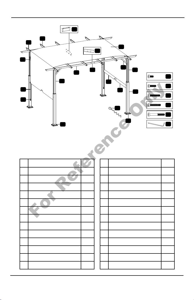
6
Description Qty Description Qty
A Upper Pole 2 N Canopy Weight Bar 2
B Upper Pole 2 O Support 8
C Long Crossbeam 4 P Stake 16
D Canopy Support 8 Q Top Slide Bar Connector 4
E Crossbeam 4 R Slide Bar Connector 4
F Lower Pole 4 S Canopy 1
GSlide Bar 4 T Hex Key 1
HCanopy Support Connector 6
I Crossbeam Connector 8 1M6x15 Bolt 72
JLong Crossbeam Connector 22M6x25 Bolt 16
KFoot 4 3M6x45 Bolt 4
L Cover 4 4M6x55 Bolt 4
MShort Canopy Weight Bar 25M6x65 Bolt 24
** WE RECOMMEND THAT YOU SAVE THE HEX KEY AND WRENCH
AND PERIODICALLY TIGHTEN ALL SCREWS.**
Parts List
L
1
2
3
4
5
T
P
K
S
F
CIA
B
O
D
E
H
J
N
M
Q
R
G
For Reference Only
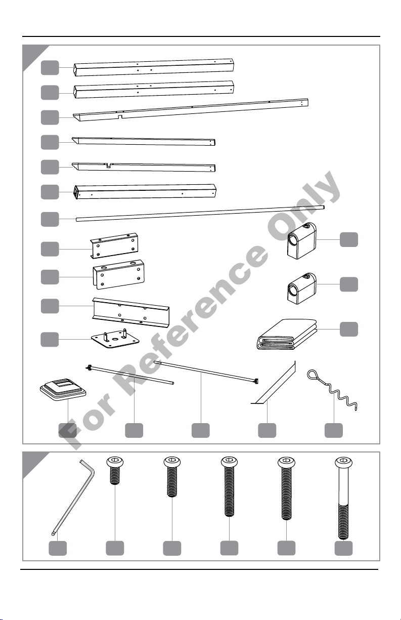
7
Hardware List
A
B
J
I
H
G
E
C
B
A
T1235
Q
L
D
F
R
S
M N O
4
K
P
For Reference Only
8
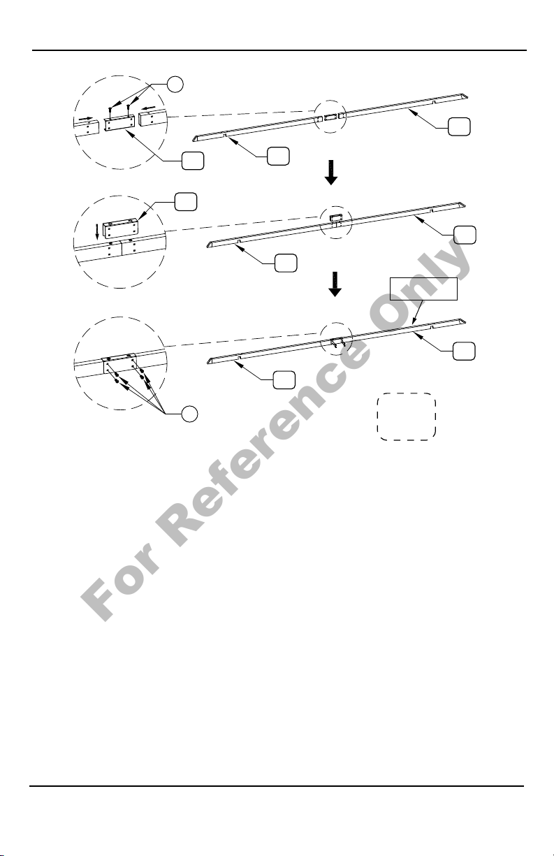
STEP 1:
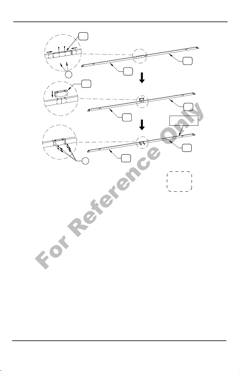
Set two Crossbeams (E) upside down on the ground as illustrated here.
Insert Canopy Support Connector (H) into the open end of Crossbeam
(E), see Fig. 1. Insert one M6x15 Bolt (1) through the bottom eyelet of
Crossbeam (E), and into the bolt-threading found at the bottom of
Canopy Support Connector (H), see Fig. 1. Insert open end of a second
Crossbeam (E) over opposite end of Canopy Support Connector (H) and
use one M6x15 Bolt (1) to secure these parts together, see Fig. 1.
Place Crossbeam Connector (I) over where these Crossbeams (E) meet
as illustrated here, see Fig. 2.
Insert two M6x15 Bolts (1) through eyelets on both ends of
Crossbeam Connector (I), and into the bolt-threading found on the
sides of Crossbeams (E) where these parts meet, see Fig. 3. Make sure all
bolts are securely tightened. Follow these steps to connect remaining
part E’s with part H and part I.
Assembly Instructions
2X
I
HE
E
E
E
E
E
1
1
This is the bottom
side of this part.
Fig. 1
Fig. 2
Fig. 3
For Reference Only
9
STEP 2:
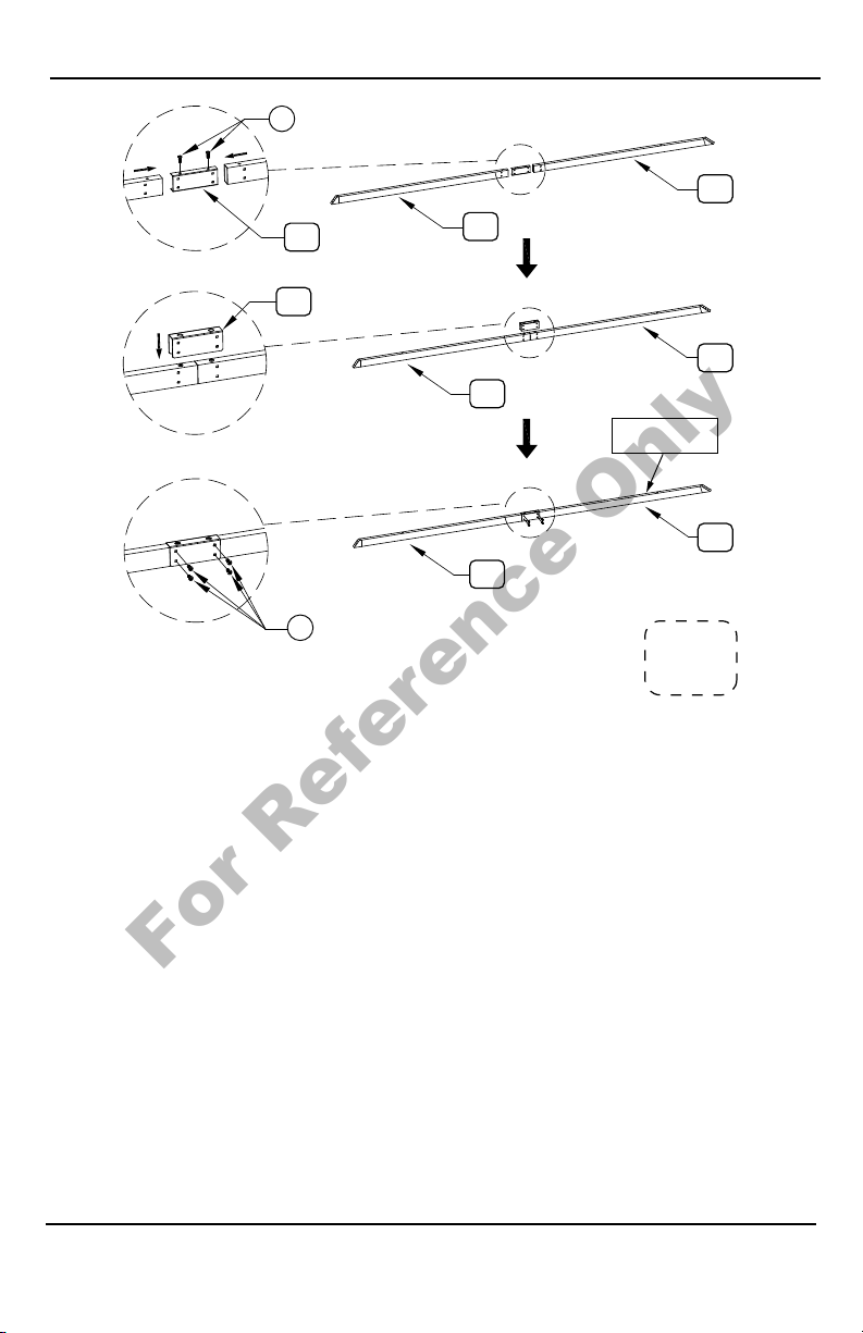
Set two Long Crossbeams (C) with the cutout notches facing up, and
on the ground as illustrated here. Insert Long Crossbeam Connector (J)
into the open end of Long Crossbeam (C), see Fig. 4. Insert one M6x15
Bolt (1) through the bottom eyelet of Long Crossbeam (C), and into the
bolt-threading found at the bottom of Long Crossbeam Connector
(J), see Fig. 4. Insert open end of a second Long Crossbeam (C) over
opposite end of Long Crossbeam Connector (J) and use one M6x15 Bolt
(1) to secure these parts together, see Fig. 4.
Place Crossbeam Connector (I) over where these Long Crossbeams (C)
meet as illustrated here, see Fig. 5.
Insert two M6x15 Bolts (1) through eyelets on both ends of
Crossbeam Connector (I), and into the bolt-threading found on the
sides of Long Crossbeams (C) where these parts meet, see Fig. 6. Make
sure all bolts are securely tightened. Follow these steps to connect
remaining part C’s with part J and part I.
Assembly Instructions
2X
I
1C
J
C
C
C
C
C
1
This is the bottom
side of this part.
Fig. 6
Fig. 5
Fig. 4
For Reference Only
10
Assembly Instructions
STEP 3:
Set two Canopy Supports (D) upside down on the ground as illustrated
here. Insert Canopy Support Connector (H) into the open end of Canopy
Support (D), see Fig. 7. Insert one M6x15 Bolt (1) through the bottom
eyelet of Canopy Support (D), and into the bolt-threading found at the
bottom of Canopy Support Connector (H), see Fig. 7. Insert open end
of a second Canopy Support (D) over opposite end of Canopy Support
Connector (H) and use one M6x15 Bolt (1) to secure these parts together,
see Fig. 7.
Place Crossbeam Connector (I) over where these Canopy Supports (D)
meet as illustrated here, see Fig. 8.
Insert two M6x15 Bolts (1) through eyelets on both ends of
Crossbeam Connector (I), and into the bolt-threading found on the
sides of Canopy Supports (D) where these parts meet, see Fig. 9. Make
sure all bolts are securely tightened. Follow these steps to connect
remaining part D’s with part H and part I.
4X
1
D
D
D
D
D
D
H
I
1
This is the bottom
side of this part.
Fig. 9
Fig. 8
Fig. 7
For Reference Only
Inhaltsverzeichnis
Sprachen:
Andere belavi Zelt Handbücher


