BLOCKsignalling SEC1A-DCC Bedienungsanleitung

SECTION CONTROLLERS
SEC1A-DCC & SEC1B-DC
The BLOCKsignalling Section Control Module is designed for DC layouts, to protect
a section of track to prevent more than one train entering that section at one time.
Monitors trains entering and leaving a section of track
Automatically sets the signal at the start of the section to danger (red)
Isolates a section of track to stop trains at the signal
Communicates to previous sections to ensure they show yellow (and
double yellow) aspects when 3- and 4-aspect signals are used
Last section can simulate returning back to clear using timers to provide
realistic operation when 3- and 4-aspect signals are used
Points which are not set in the train’s favour can force the signal to danger
Signal can be forced to danger by an external input (useful for starter
signals)
Suitable for 2-, 3-, and 4-aspect led signals (SEC1A-DC for common-
cathode and SEC1B-DC for common-anode).
Bidirectional running with 2-aspect signalling at each end of the line
New: Additional Station Stop Modes
New: Additional Dapol output
Remembers whether the section is occupied after the power is removed
and automatically restores the signals after power returns.
Simple to setup, but also fully configurable to provide the most realistic
operation
Requires a 12V DC Power Supply

Page 2 of 42
BLOCKsignalling www.blocksignalling.co.uk
Introduction
The BLOCKsignalling Section Control Module is designed to protect a section of
track to prevent more than one train entering that section at one time (see later for
details of the Station Stop Modes).
At the entrance to the section there is a signal and a short isolated piece of track
which can be energised and de-energised by a relay built-in to the module. There is
also an infra-red sensor which is located below the track which is able to detect
trains passing the signal.
The isolated section of track is normally powered via the relay and the signal
normally shows a green aspect.
At the start of the section, the infra-red sensor is continuously looking for a trains
passing, and as soon as it detects one, it switches the signal to red and disconnects
the power from the isolated section of track, stopping any approaching train in front
of the red signal (see later for bidirectional running).
The module then uses a second infra-red sensor located at the exit from the section
of track to detect when the train has completely left the section.
When this is confirmed, the signal at the entrance to the block is switched from
danger back to green (if a 2-aspect signal is used). The isolated track section at the
entrance is also re-energised and any waiting train will then move away past the
signal.
If 3- or 4-aspect signals are connected, then information from the following blocks is
used to switch the signals to show yellow or double yellow. The interconnection
between the modules carries coded information of the status of the block ahead.
In 2-aspect mode, a Dapol signal can be driven via a relay connected to CH5 for
some of the modes (2, 7 and 8). There are also station stop modes. These are
discussed in further detail later.
Bidirectional Running
There are two programs for bi-directional running with 2-aspect signals.
The first uses both sensors to detect trains entering the section. When a train
enters, the signal outputs are set to red. The sensors are checked alternately.
When the train has completely entered, the module then begins checking both
sensors to see if a train leaves the section.

Page 3 of 42
BLOCKsignalling www.blocksignalling.co.uk
The sensors are checked alternately, and if a train is detected, the module waits until
the train has cleared that sensor before setting the signals to green.
The second mode for bi-directional running uses both sensors to detect trains
entering the section. When a train enters, the signal outputs are set to red. The
sensors are checked alternately.
The module remembers the entry sensor and then begins checking the other sensor
to see if a train leaves the section.
If a train is detected leaving via the exit sensor, the module waits until the train has
cleared that sensor before setting the signals to green.
In these two modes, the isolated track sections are not used.
Power-Off Memory
There is a new setting to record whether there was a train in the section at the time
the power is turned off. When the power it turned on again, the information will be
reloaded from memory and so the correct status will be indicated on the signals and
relayed to any interconnected modules.
This feature is also used to remember the directional train are running when the
bidirectional mode is used.
This feature is disabled by default.
Page 4 of 42
BLOCKsignalling www.blocksignalling.co.uk
Module Connections
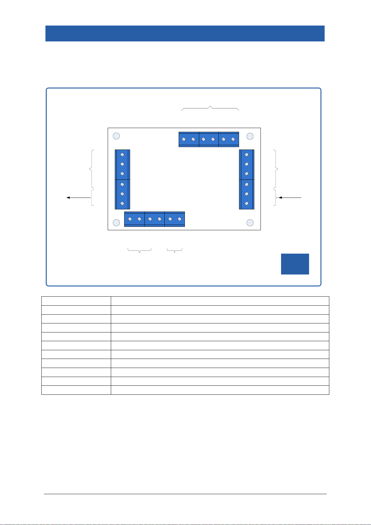
The diagram below shows the connections to the module.
Terminals
Function
ACIN/+, ACIN/-
Power supply input
S
Track suppression connection (not used)
NC
Relay contact: Normally Closed
COM
Relay contact: Common
NO
Relay contact: Normally Open
SIG+,GND
Connection to previous block for interlocking (note 1)
A1,K1,C1,E1
Sensor 1 connections
CH1-CH5,VOUT
Connections for led signals
A2,K2,C2,E2
Sensor 2 connections
A+,K-
Connection to next block for interlocking (note 2)
Note 1: the connection between the modules carries coded information about the
presence of trains in this section (and following sections if appropriate). This
information is used to switch the yellow aspects on the signals (3- and 4-aspect
only).
Note 2: Optionally connecting steady 12V DC to this input, tells the module the next
section is occupied.
BLOCK
signalling
CH3
CH2
CH1
VOUT
COM
NO
S
NC
AC/IN+
AC/IN-
A2
K2
C2
E2
A+
K-
SENSOR 2
CONNECTIONS
LED SIGNAL
CONNECTIONS
SUPPLY
RELAY
CONTACTS
www.blocksignalling.co.uk
CH5
CH5
A1
K1
C1
E1
SIG+
GND
SENSOR 1
CONNECTIONS
IN FROM
NEXT BLOCK
OUT TO
PREVIOUS BLOCK
POWER
TRACK
SUPRESSOR

Page 5 of 42
BLOCKsignalling www.blocksignalling.co.uk
Power Supply
The controller is designed for use with a 12V DC plug-top type power supply.
The current consumption is 0.25A, and a power supply rated at 0.5A to 1A is
recommended.
Do not connect to the auxiliary terminals on the back of a train controller as the
module may operate unpredictably and could be damaged. These outputs are often
unsuitable as they are designated as a fairly basic power outputs for accessories
such as points motors and may not be smooth or stable.
If a DC power supply is connected with incorrect polarity no damage will occur, but
the module will not operate.

Page 6 of 42
BLOCKsignalling www.blocksignalling.co.uk
Connection for a Single Block
The control of one block section consists of the following parts:
1. An entry sensor, to detect a train entering the section (Sensor 1).
2. An exit sensor, to detect a train leaving the section (sensor 2).
3. A section of isolated track preceding the signal (there are track breaks in only the
right-hand rail), which is controlled by a relay on the block controller stop a train at
the signal when the signal is at danger (this is not used with bidirectional running).
4. Connections to and from adjacent sections to communicate information about
which blocks are occupied (not required when 2-aspect signals are used).
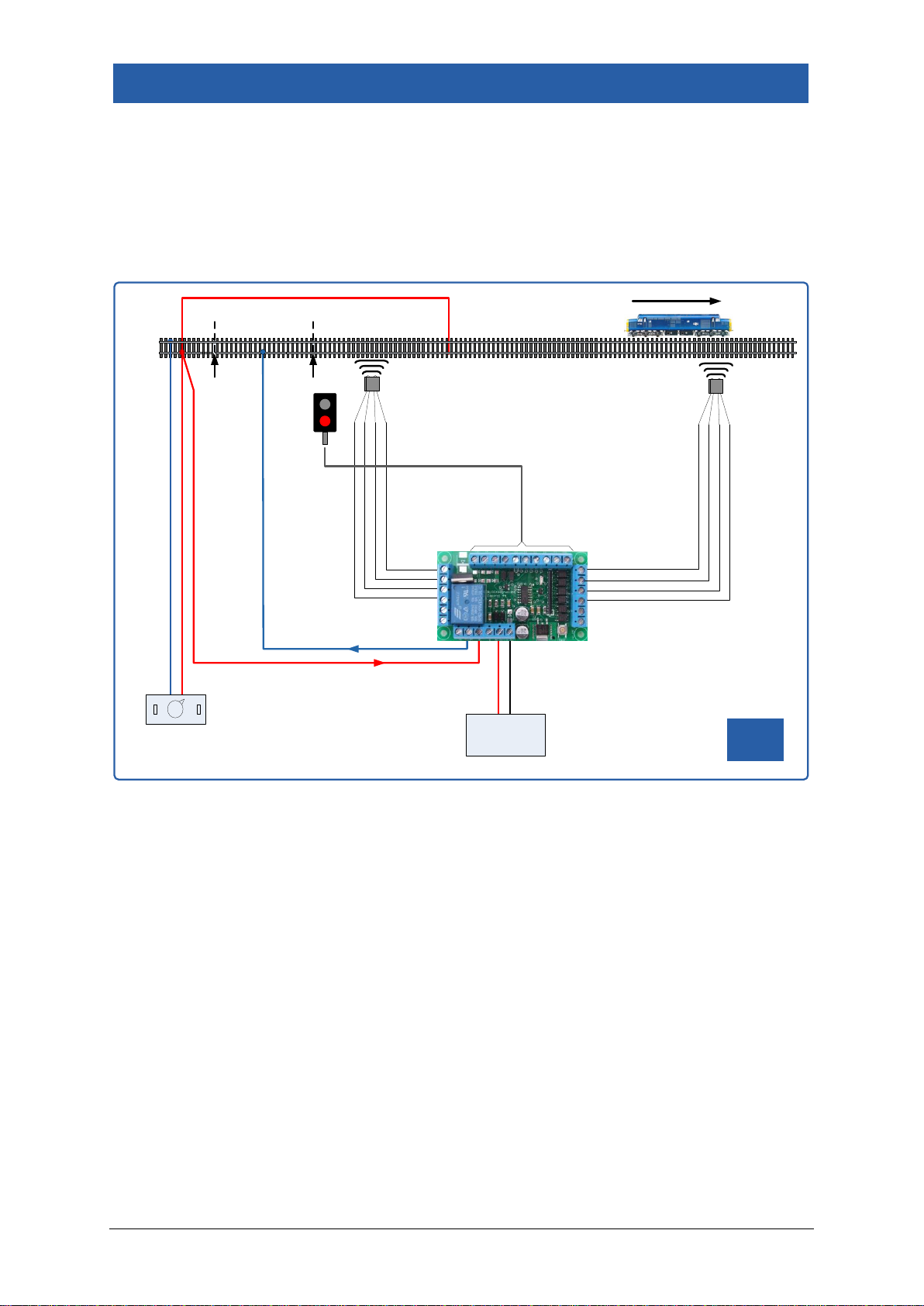
The following diagram shows the connections when 2-aspect signals are used.
BLOCK
signalling
POWER
SUPPLY
DC CONTROLLER
ENTRY SENSOR
(SENSOR 1)
TRACK
BREAK
ISOLATED SECTION
(RIGHT RAIL ONLY)
TRACK
BREAK EXIT SENSOR
(SENSOR 2)
Page 7 of 42
BLOCKsignalling www.blocksignalling.co.uk
2-Aspect signals (Unidirectional Running)
If trains only run in one direction on the line, an isolated section can be placed
preceding the signals. When a train is detected entering the section, the module will
operate the signal and isolate the track section to stop any following trains entering
the same section.
BLOCK
signalling
POWER
SUPPLY
DC CONTROLLER
ENTRY SENSOR
(SENSOR 1)
TRACK
BREAK
ISOLATED SECTION
(RIGHT RAIL ONLY)
TRACK
BREAK EXIT SENSOR
(SENSOR 2)
Page 8 of 42
BLOCKsignalling www.blocksignalling.co.uk
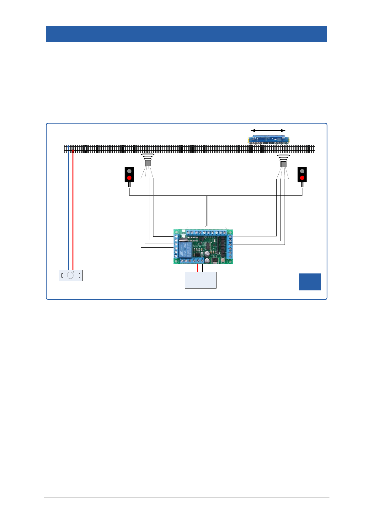
2-Aspect signals (Bi-directional Running)
If bidirectional running is being used with 2-aspect signals, then both the signals are
controlled by one module.
An isolated track section is not used and the module does not stop trains in this
mode.
BLOCK
signalling
POWER
SUPPLY
DC CONTROLLER
ENTRY SENSOR
(SENSOR 1) ENTRY SENSOR
(SENSOR 2)
Page 9 of 42
BLOCKsignalling www.blocksignalling.co.uk
Connection Multiple Simple Blocks
When 2-aspect signals are used, there are no interconnections between adjacent
sections.
If 3- or 4-aspect signals are used, additional connections are required between the
modules to communicate which sections in front of the train are occupied (otherwise
yellow signal aspects will not be shown).
To connect blocks together, the Train in Section (TIS) wiring is linked from one block
to the next.
Page 10 of 42
BLOCKsignalling www.blocksignalling.co.uk
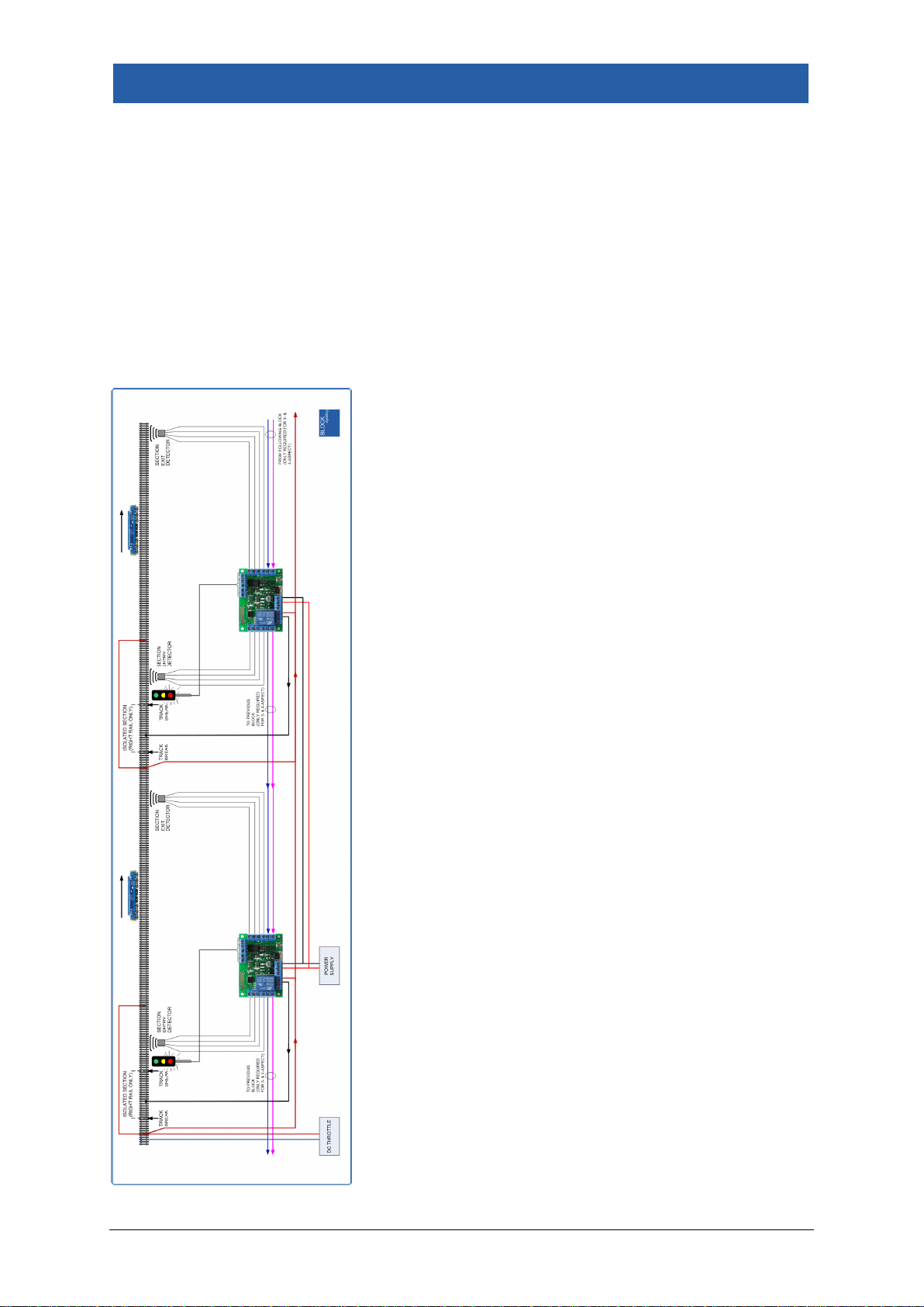
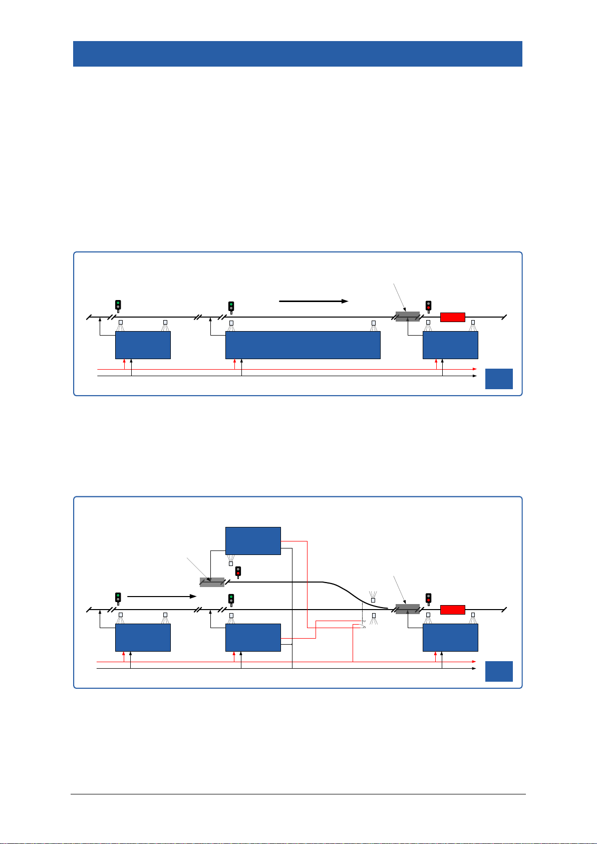
2 Aspect Led Signal Example
In the following example, 2 aspect led signals are used and the diagram has been
simplified to show only the relevant wiring. The train has driven from the left to the
right, and is currently in Block 3.
The block section controller for Block 3 has detected the train enter the section, and
has set the signal to danger (red) and isolated the track section to prevent any other
trains entering.
There is no need to connect the sections together as with 2-aspect signalling, the
signal preceding a section only shows the occupancy of the section itself.
If there are points in use, we can feed 12V into the train in section inputs via the
points auxiliary contacts, and this will force one of the associated signals to red.
SEC SEC
TRAIN DIRECTION
SEC
BLOCK 1 BLOCK 2 BLOCK 3
BLOCK
signalling
TRAIN
TRACK SECTION
ISOLATED
BLOCK SECTION
CONTROLLER BLOCK SECTION
CONTROLLER
TRAIN DIRECTION
BLOCK SECTION
CONTROLLER
BLOCK SECTION
CONTROLLER
BLOCK 1 BLOCK 2 BLOCK 3
BLOCK 4
BLOCK
signalling
+12V
TRAIN
TRACK SECTION
ISOLATED
0V
TRACK SECTION
ISOLATED
Dieses Handbuch passt für folgende Modelle
1
Inhaltsverzeichnis
Andere BLOCKsignalling Controller Handbücher


