M3575R
4
1. INTRODUCTION..........................................................................................................................7
1.1. Who should use ............................................................................................................................ 7
1.2. Purpose and Scope........................................................................................................................7
1.3. Manual version and change record...............................................................................................7
Figure 1-1: Typical M3575R-B10 Unit....................................................................................................7
1.4. Symbol Conventions Used in this Manual and on Equipment.....................................................8
2. PRODUCT DESCRIPTION.............................................................................................................9
2.1. Related Docs.................................................................................................................................9
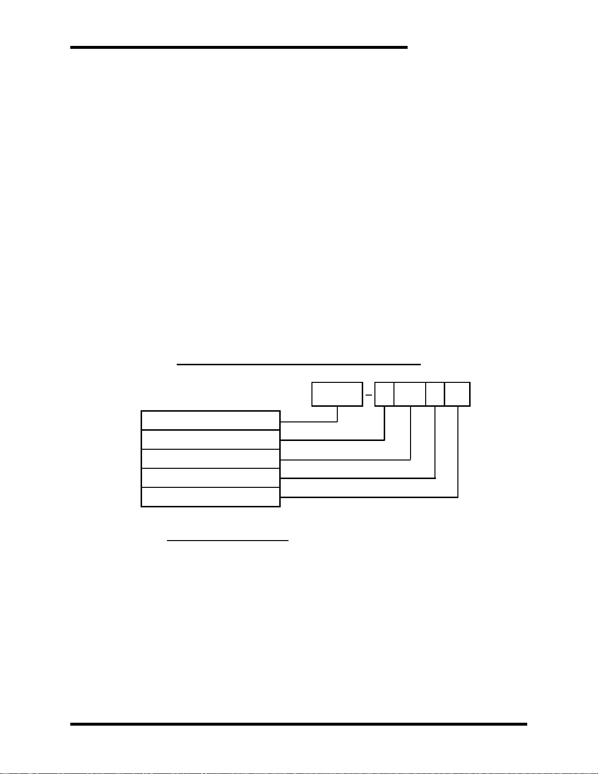
2.2. Part Number Breakdown ..............................................................................................................9
Figure 2-1: Example of Part Number Breakdown....................................................................................9
Table 2-1: AC Voltage Rating ...............................................................................................................10
Table 2-2: Example of Horsepower Rating............................................................................................10
Table 2-3: Chassis Styles .......................................................................................................................10
Table 2-4: Cooling Options....................................................................................................................11
2.3. General Specifications Chart......................................................................................................11
Table 2-5: General Specifications..........................................................................................................11
2.4. General Precautions and Safety Warnings .................................................................................12
3. INSTALLATION INSTRUCTIONS................................................................................................13
3.1. Environment ...............................................................................................................................13
3.2. Unpacking................................................................................................................................... 13
Figure 3-1: M3575R Mounting Orientation...........................................................................................13
3.3. Mounting ....................................................................................................................................13
3.4. Wiring and Customer Connections.............................................................................................14
3.4.1. Power Wiring..................................................................................................................14
Table 3-1: Power Wiring Chart..............................................................................................................14
3.4.2. I/O Wiring.......................................................................................................................15
Table 3-2: Terminal Block Specifications..............................................................................................15
Figure 3-2: Typical Braking Resistor Field Connections.......................................................................16
3.5. Typical Configurations...............................................................................................................17
Figure 3-3: Typical Braking Interconnection Diagram ..........................................................................17
Figure 3-4: Typical Braking Interconnection Diagram With Parallel Load Modules............................17
4. OPERATION..............................................................................................................................19
4.1. Functional Description ...............................................................................................................19
4.2. Features....................................................................................................................................... 19
4.2.1. Terminal Strip I/O...........................................................................................................19
4.3. Startup......................................................................................................................................... 19
4.3.1. Pre-power Checks ...........................................................................................................19
4.3.2. Startup Procedure and Checks......................................................................................... 19
4.4. Operational Adjustments............................................................................................................19
5. MAINTENANCE AND TROUBLESHOOTING...............................................................................21
5.1. Periodic Testing..........................................................................................................................21
5.2. Maintenance Items......................................................................................................................21
5.3. Troubleshooting..........................................................................................................................21
5.3.1. Drive trips on over-voltage or self-limits its decel rate...................................................21
5.3.2. The cooling fan doesn't turn on.......................................................................................21
5.3.3. Over-Temp Contact is open ............................................................................................ 22
5.3.4. Over-Temp Contact does not open on Over-Temp condition.........................................22
5.4. Technical Help –Before you call...............................................................................................22