
Boser HS-2606 Bedienungsanleitung

HS-2606
ULV Intel® Celeron® processor
Embedded Engine Board
•CompactFlash•PCMCIA•Mini PCI•
•CRT/Panel•TV-Out•LAN•Audio•
•ATA/33/66/100•4 COM•USB2.0•WDT•

Copyright Disclaimers
The accuracy of contents in this manual has passed thorough checking and review before
publishing. BOSER Technology Co., Ltd., the manufacturer and publisher, is not liable for
any infringements of patents or other rights resulting from its use. The manufacturer will
not be responsible for any direct, indirect, special, incidental or consequential
damages arising from the use of this product or documentation, even if advised of
the possibility of such damage(s).
This manual is copyrighted and BOSER Technology Co., Ltd. reserves all
documentation rights. Unauthorized reproduction, transmission, translation, and
storage of any form and means (i.e., electronic, mechanical, photocopying, recording)
of this document, in whole or partly, is prohibited, unless granted permission by BOSER
Technology Co., Ltd.
BOSER Technology Co., Ltd. reserves the right to change or improve the contents of
this document without due notice. BOSER Technology Co., Ltd. assumes no
responsibility for any errors or omissions that may appear in this manual, nor does
it make any commitment to update the information contained herein.
T
T
Tr
r
ra
a
ad
d
de
e
em
m
ma
a
ar
r
rk
k
ks
s
s
BOSER is a registered trademark of BOSER Technology Co., Ltd.
ISB is a registered trademark of BOSER Technology Co., Ltd.
Intel is a registered trademark of Intel Corporation.
AMI is a registered trademark of AMI Software, Inc.
AMI is a registered trademark of AMI Software, Inc.
All other trademarks, products and or product names mentioned herein are
mentioned for identification purposes only, and may be trademarks and/or
registered trademarks of their respective companies or owners.
© Copyright 2008 BOSER Technology Co., Ltd.
All Rights Reserved.
Edition 2.1, February 26, 2008

Table of Contents
Chapter 1 General Description ..................................1
1.1 Major Features....................................................................... 2
1.2 Specifications ........................................................................ 3
1.3 Board Dimensions................................................................. 4
Chapter 2 Unpacking ..................................................5
2.1 Opening the Delivery Package............................................. 5
2.2 Inspection............................................................................... 5
Chapter 3 Hardware Installation ..............................7
3.1 Before Installation ................................................................. 7
3.2 Board Layout ......................................................................... 8
3.3 Jumper List ............................................................................ 9
3.4 Connector List ....................................................................... 9
3.5 Configuring the CPU ............................................................. 9
3.6 System Memory ................................................................... 10
3.7 CMOS Data Clear................................................................. 10
3.8 Power and Fan Connectors................................................ 10
3.9 System Front Panel Control ............................................... 11
3.10 VGA Controller .................................................................... 12
3.11 TV-Out Connector ............................................................... 14
3.12 Ethernet Connector............................................................. 14
3.13 Audio Connectors ............................................................... 15
3.14 PCI E-IDE Drive Connector................................................. 16
3.15 Serial Port Connectors ....................................................... 17
3.16 USB Connector .................................................................... 17
3.17 Keyboard/Mouse Connectors ............................................ 18
3.18 Watchdog Timer .................................................................. 18
3.19 GPIO Function ..................................................................... 19
3.20 Mini PCI Slot......................................................................... 20
3.21 CompactFlashConnector................................................ 20
3.22 PCMCIA Connector ............................................................. 20

Chapter 4 AMI BIOS Setup..................................... 21
4.1 Starting Setup...................................................................... 21
4.2 Using Setup ......................................................................... 22
4.3 Main Menu............................................................................ 23
4.4 Standard CMOS Setup ........................................................ 24
4.5 Advanced CMOS Setup ...................................................... 25
4.6 Advanced Chipset Setup.................................................... 26
4.7 Power Management Setup ................................................. 27
4.8 PCI / Plug and Play Setup................................................... 28
4.9 Peripheral Setup.................................................................. 29
4.10 Auto-Detect Hard Disks ...................................................... 30
4.11 Change Supervisor/User Password .................................. 31
4.12 Auto Configuration with Optimal Settings ....................... 32
4.13 Auto Configuration with Fail Safe Settings ...................... 33
4.14 Save Settings and Exit........................................................ 34
4.15 Exit Without Saving............................................................. 35
Chapter 5 Software Utilities..................................... 37
5.1 VGA Driver Installation ....................................................... 37
5.2 LAN Driver Installation........................................................ 47
5.3 Audio Driver Installation..................................................... 57
5.4 USB2.0 Driver Installation .................................................. 63

Safety Instructions
Integrated circuits on computer boards are sensitive to static electricity. To
avoid damaging chips from electrostatic discharge, observe the following
precautions:
Do not remove boards or integrated circuits from their anti-static packaging
until you are ready to install them.
Before handling a board or integrated circuit, touch an unpainted portion of
the system unit chassis for a few seconds. This helps to discharge any static
electricity on your body.
Wear a wrist-grounding strap, available from most electronic component
stores, when handling boards and components. Fasten the ALLIGATOR clip
of the strap to the end of the shielded wire lead from a grounded object.
Please wear and connect the strap before handle the product to ensure
harmlessly discharge any static electricity through the strap.
Please use an anti-static pad when putting down any components or parts or
tools outside the computer. You may also use an anti-static bag instead of
the pad. Please inquire from your local supplier for additional assistance in
finding the necessary anti-static gadgets.
NOTE: DO NOT TOUCH THE BOARD OR ANY OTHER SENSITIVE
COMPONENTS WITHOUT ALL NECESSARY ANTI-STATIC
PROTECTIONS.


1
Chapter 1
General Description
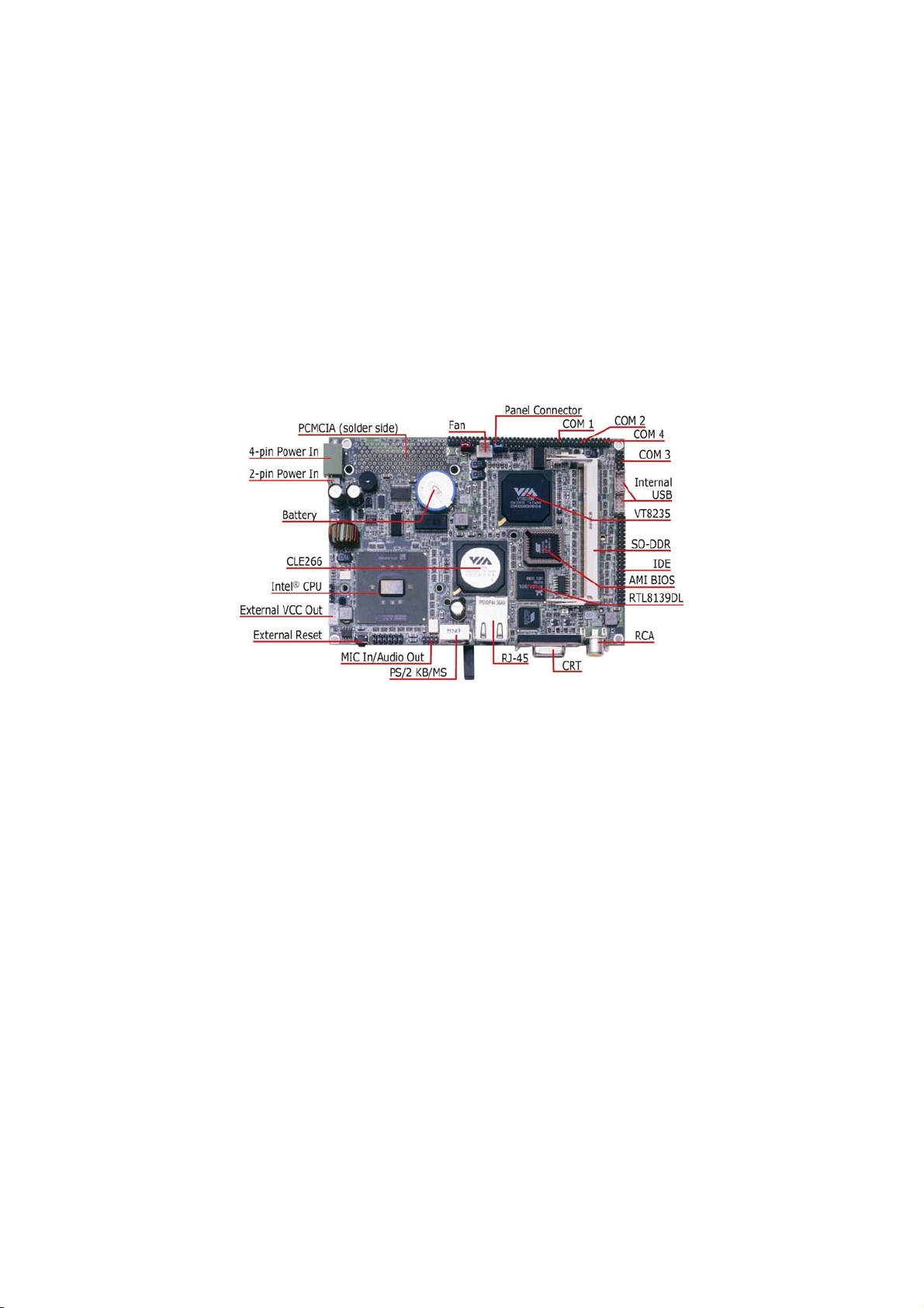
The HS-2606 is a 100/133MHz FSB VIA CLE266/VT8235
chipset-based board designed for Mini PCI Local Bus ULV Intel®
Celeron® processor 400/650MHz. These features combine and make
the HS-2606 and ideal all-in-one industrial single board computer.
Additional features include and enhanced I/O with CF, PCMCIA,
CRT/Panel, audio, LAN TV-Out, 4 COM, and USB2.0 interfaces.
Its onboard ATA/33/66/100 to IDE drive interface architecture allows
the HS-2606 to supports data transfers of 33, 66 or 100MB/sec. To one
IDE drive connection. Designed with the VIA CLE266/VT8235 core
logic chipset, the board supports VIA Eden 1GHz Embedded CPU. The
VIA CLE266 integrated S3 3D supports CRT display up to 1400 x 1050
@ 60Hz, and panel display up to 1400 x 1050.
HS-2606 offers PCMCIA connector and CompactFlash reader in
addition. +10~+30V wide range single DC power in can make HS-2606
suitable for all kinds of environments even more.
2
System memory is also sufficient with the one 200-pin SO-DDR socket
that can supports up to 1GB.
Additional onboard connectors include 4 USB2.0 port providing faster
data transmission. And one external RJ-45 connector for 10/100 Based
Ethernet use.
1.1 Major Features
The HS-2606 comes with the following features:
ULV Intel® Celeron® embedded 400/650MHz
One SO-DDR socket with a max. capacity of 1GB
VIA CLE266/VT8235 chipset
Winbond W83697UF super I/O chipset
VIA CLE266 graphics controller
RealTek RTL8139DL Ethernet controller
AC97 3D audio controller
Fast PCI ATA/33/66/100 IDE controller
CF, PCMCIA, 4 COM, 4 USB2.0
TV-Out function
+10~+30V wide range single DC power in

3
1.2 Specifications
CPU: ULV Intel® Celeron® processor 400/650MHz
Memory: One SO-DDR socket supports up to 1GB
Chipset: VIA CLE266/VT8235
I/O Chipset: Winbond W83697UF
CompactFlash: One, Type I/II IDE interface adapter
PCMCIA: Two PC Card or CardBus slots
PCI Slot: One, Type I mini PCI slot
VGA: VIA CLE266 integrated S3 3D supports AGP Bus and Hardware
MPEG-2
TV-Out: Supports PAL or NTSC TV system
Ethernet: RealTek RTL8139DL 10/100 Based LAN
Audio: AC97 3D audio controller
IDE: One 2.0-pitch 44-pin IDE connector
Serial Port: 16C550 UART-compatible RS-232 x 4 serial ports with
16-byte FIFO
USB: 4 internal USB2.0 ports
Keyboard/Mouse: PS/2 6-pin Mini DIN
BIOS: AMI PnP Flash BIOS
Watchdog Timer: Software programmable time-out intervals from
1~255 sec.
CMOS: Battery backup
Power In: +7~+26V wide range single DC power in
Temperature: 0~+60°C (operating)
Dimensions: 14.5(L) x 10.2(W) cm

4
1.3 Board Dimensions
Dieses Handbuch passt für folgende Modelle
1
Inhaltsverzeichnis
Andere Boser Hauptplatine Handbücher

Boser
Boser HS-4020 Bedienungsanleitung

Boser
Boser HS-3000/4M Bedienungsanleitung

Boser
Boser HS-7250 Bedienungsanleitung

Boser
Boser BPC-6169 Bedienungsanleitung

Boser
Boser HS-1770 Bedienungsanleitung

Boser
Boser HS-2604 Bedienungsanleitung

Boser
Boser HS-4600 Bedienungsanleitung

Boser
Boser HS-4701 Bedienungsanleitung
Beliebte Hauptplatine Handbücher anderer Marken


Telit Wireless Solutions
Telit Wireless Solutions SL869-3DR Bedienungsanleitung

Gigabyte
Gigabyte GA-9IVDT Bedienungsanleitung

Texas Instruments
Texas Instruments ADS8372EVM Bedienungsanleitung

Commell
Commell MS-C73 Bedienungsanleitung

IBT Technologies
IBT Technologies MB860 Bedienungsanleitung

Nvidia
Nvidia TEGRA DG-04927-001_V01 Bedienungsanleitung


