BUG-O BGW-1000 Technisches Referenzhandbuch

INSTRUCTIONS
aNd
PaRTS MaNUaL
aLL TIME GIRTH WELdER
BGW-1000 BGW-2000
a dIVISION OF WELd TOOLING CORPORaTION
280 TECHNOLOGY dRIVE CaNONSBURG, PENNSYLVaNIa 15317-9564 USa
PHONE: 1-412-331-1776 http://www.bugo.com FaX: 1- 412- 331- 0383
Please record your equipment identication information below for future reference. This information can be found
on your machine nameplate.
Model Number
Serial Number
Date of Purchase
Whenever you request replacement parts or information on this equipment, always supply the information you have
recorded above.
LIT-BGW-IPM-1209

SAFETY
PROTECT YOURSELF AND OTHERS FROM SERIOUS INJURY OR DEATH. KEEP CHILDREN
AWAY. BE SURE THAT ALL INSTALLATION, OPERATION, MAINTENANCE AND REPAIR
PROCEDURES ARE PERFORMED ONLY BY QUALIFIED INDIVIDUALS.
EQUIPMENT DAMAGE
POSSIBLE.
ELECTRIC SHOCK can kill.
1) The equipment is not waterproof. Using the
unit in a wet environment may result in
serious injury. Do not touch equipment when
wet or standing in a wet location.
2) The unused connectors have power on
them. Always keep the unused connectors
covered with the supplied protective panels.
Operation of the machine without the
protective panels may result in injury.
3) Never open the equipment without first
unplugging the power cord or serious injury
may result.
4) Verity the customer-supplied power connec-
tions are made in accordance with all
applicable local and national electrical safety
codes. If none exist, use International
Electric Code (IEC) 950.
5) Never remove or bypass the equipment
power cord ground. Verify the equipment is
grounded in accordance with all applicable
local and national electrical safety codes. If
none exist, use International Electric Code
(IEC)950.
READ INSTRUCTIONS.
Read the instruction manual before installing and
using the equipment.
1) Do not plug in the power cord without first the
verifying the equipment is OFF and the cord
input voltage is the same as required by the
machine or serious damage may result.
2)Always verity both the pinion and wheels are
fully engaged before applying power or equip-
ment damage may occur.
3) Do not leave the equipment unattended.
Remove from the worksite and store in a safe
location when not in use.
1) Never try to stop the pinion from moving except
by removing power or by using the STOP
control.
2) Do not remove any protective panels, covers or
guards and operate equipment.
MOVING PARTS can
cause serious injury.
FALLING EQUIPMENT can
cause serious personal injury
and equipment damage.
Faulty or careless user installation is possible.
As a result, never stand or walk underneath
equipment.

PRECAUTIONS:
1) Some plasma or welding cables are strong sources of high frequency interference.
NEVER lay a plasma or welding cable across the controls of the machine.
2) Always physically separate the plasma or welding cable leads from the machine
cables. For example, the plasma or welding cable leads should NEVER be bundled
with a pendant cable or the machine power cord. Maximize the separation between
any machine cables and the plasma or welding cables.
3) Strictly follow the grounding procedures specified for the plasma or welding unit.
NOTE: Some plasma and welding units produce exceptionally large amounts of high
frequency noise. They may require a grounding rod be driven into the earth within six
feet (2 meters) of the plasma or welding unit to become compatible with an automatic
cutting or welding process.
4) If the high frequency is produced using a spark gap, adjust the points so the gap is as
small as possible. The larger the gap, the higher the voltage and the higher the inter-
ference.
5) Some plasma or welding units will inject high frequency interference into theAC
power line. Use separate power line branches whenever possible to power the
plasma or welding source and the machine. Do not plug them into the same outlet
box.
6) High frequency noise may enter the machine through the plasma or welding supply
remote contactor leads. Some plasma and welding sources can produce noise spikes
of up to several thousand volts. These sources are not compatible with automated
cutting and welding equipment. It is recommended that the remote contactor leads on
these plasma or welding sources not be connected to the machine. An alternate
solution is to purchase a separate remote contactor isolation box.
HIGHFREQUENCYWARNINGS
WARNING: HIGHFREQUENCY CAN EFFECT MACHINE
OPERATIONAND THEREFORE, WELD QUALITY.
SPECIAL PRECAUTIONS ARE REQUIRED WHEN USING PLASMA,
TIG OR ANY WELDING PROCESS THAT USES HIGH FREQUENCY
TO STRIKE AN ARC.
Read the precautions below before installing and using the equipment.

4
5 ........... General Description
5 ........... General Description / Single and Double Sided Welding
5 ........... General Description / Welding Process
5 ........... Technical Specifications
6 ........... Key Components
6 ........... Key Components / Main Frame
6 ........... Key Components / Dual Motor Drive
6 ........... Key Components / Welding Gear
7 ........... Key Components / Weld Head Assembly
7 ........... Key Components / Control
10 .......... Key Components / Flux Recovery
10 .......... Key Components / Electrical Cabinet & Power Supply Storage
11 .......... Key Components / Electric Flux Winch
11 .......... Installation andOperations
11 .......... Installation and Operations / Frame Setup
13 .......... Installation and Operations / Master Control Connection
13 .......... Installation andOperations / Installation
14 .......... Installation and Operations / Input Connection
14 .......... Installation and Operations / Operation
15 .......... Installation and Operations / Welding
16 .......... Welding Procedure Guidelines
16 .......... Welding Procedure Guidelines / Joint Design
16 .......... Welding Procedure Guidelines / Typical Welding Parameters
19-20 ..... Troubleshooting
21 .......... Maintenance
22 .......... Girth Welder / Parts List
23 .......... Girth Welder / Exploded View
24 .......... Control Box Assembly / Parts List
25 .......... Control Box Assembly / Exploded View
26 .......... Guide Wheel Assembly / Parts List
27 .......... Guide Wheel Assembly / Exploded View
28 .......... Operations Schematic
29 .......... Wiring Diagram
30 .......... Warranty
TABLE OF CONTENTS PAGE
BUG-OALL TIME GIRTH WELDER
INSTRUCTIONS AND PARTS MANUAL
PAGE

5
GENERALDESCRIPTION
The (BGW) Automatic Girth Welder is a self-propelled machine for horizontal girth (3 o’clock) welding of large
storage tank having 6' – 10.5' (1.8 – 3.2m) high plate courses.
The unit is supported by the shell plates to be welded; the machine has its own welding head, controls, flux belt
assembly and flux recovery unit.
The standard welding equipment integrated is the Lincoln Electric USA submerged arc welding system.
Single and Double Sided Welding
With variations in designs; the Automatic Girth Welder can perform single sided (BGW-1000) or double sided
(BGW-2000) operations.
BGW-1000
The single sided unit, BGW-1000 is the mostcommonly used unit due to its light weight and simplicity. It requires
only one operator.
BGW-2000
Designed with the same principle as BGW-1000, but with an “A” frame that carries one set of weld head on each
side.
One side, referred to as the master, can be used by itself for one side welding.The second side (slave) is hinged
to the top of the master frame and is used when welding two sides.
Theoperatorcan movefreelyfrom oneside of themachine toanotherby climbingupthe ladderon one sideto the
common roof of the double sided machine.
A safety rail is provided at the roof of the main frame for safety purpose.
The BGW-2000 requires two welding power supplies. Each unit has a flux recovery unit and controls.
Welding Process
The BGW-1000 is normally equipped for single wire submerged arc welding.
Typical weld procedure called for a welding travel speed of around 18 in/min (450mm/min), 400A, 28-30V and
WFS of 91'' (2300 mm). Single torch deposition rate is approximately 11 lbs/hr. (5kg/hr.)
TECHNICALSPECIFICATIONS
1. Inputvoltage: 3 phase, 380V±10% (Standard)
* Consult factory for non-standard power input
2. Inputfrequency: 50Hz±5% / 60Hz±5%
3. Operation temperature: 14°F--------+122°F(-10°C--------+50°C); Relative humidity: >90%;
4. Environmentalprotection: IP23 grade: F
5. Tank diameteroperationrange: > 15' (4.5 M)
6. Operation tank shell plate width: 6'-10.5' (1.8-3.2m) [Standard]
Max. 15' (4.5m) [Special]
* Models and specifications subject to change without notice.

6
KEY COMPONENTS
Main Frame
The Main frame of the girth welder is constructed of structural steel and square tube members. The slide square
tube mechanism with locking pins and pin holes is used to adjust the frame height for welding different sizes
of shell plates. The main frame of the girth welder is designed to support 550 lbs (250 kg) of weight, or enough
for two operators.
The frame contains two serrated hardened steel anged drive wheels manually adjusted to ride tank diameters
down to a minimum of 15’ (4.5 m.) The distance between wheel anges is 1.8’’ (45mm) [standard] to accommodate
the shell wall thickness.
The machine frame is equipped with a hand railed operator platform with seat, a ladder provides a means for
operator to climb to the roof and access to the electric ux winch and separator tank for ux rell.
Guide wheel assembly at the lower end of the frame to simplify loading and
unloading the machine on the tank. Canvas curtains offer arc and operator
protection in windy conditions.
Dual Motor Drive
Each single anged drive wheel is driven by an individual SAW motor /
reducer to provide extra tracking force to prevent slipping that could cause
weld defects. Drive motors are enclosed inside the frame top section with
aluminum panel for good weather protection.
Speeds for both motors are electronically synchronized and governed by an
inverter for accurate speed travel.
AC inverter:
1. Single-phase 220VAC input voltage
2. Automatic lift in torsion, 150% lift torsion in 6Hz.
3. Fully programmed & calibrated in factory
4. Soft PWM, running in low noise
5. 15 speed, PID, 4-20 MA input
6. Provides RS-485 communication
Caution: All the inverter drives inside the BGW control are pre-programmed before the girth welder is deliv-
ered to users on site. Please consult factory if re-programming is required.
The SEW motors and reducer requires minimal maintenance with advantages of
low noise & vibration, with 96% high efciency through the reducer. It consists of
a high rigid housing and spur gear; all parts are precisely machined with minimum
tolerance for accurate travel mechanism.
Welding Gear
The standard welding equipment supplied is the Lincoln USA NA3 control and weld
head tted with nozzle, wire feed rolls, wire straightener, and 50lbs (23Kg) wire reels
for feeding up to 3.2 mm (1/8’’) diameter wire.
Lincoln USA DC600 is the standard power supply
for the girth welder. Standard input power is 380V/3ph/50Hz and the line power
requirement is 40kVA. Other voltages and frequencies are available, please
consult factory for details.
Please refer to Lincoln’s NA3 and DC600 Instruction manuals for more informa-
tion on their welding equipment.
Power supplies are installed on a steel storage case with the electrical cabinet
for weather protection.

7
Weld Head Assembly
The BGW weld head is mounted on a manual cross slide system,
which allows the operator complete control of wire placement and
joint tracking.
Due to the lack of visibility of the submerged arc welding process, a
laser pointer is mounted on the nozzle to provide a position reference
for operator while welding.
Control
Welding Control
The Lincoln USA NA3 welding control is normally supplied with the
girth welder. It is mounted on the right hand side of the main frame for
the operator to access easily. Directly on top of the NA3 control is the
BGW master control.
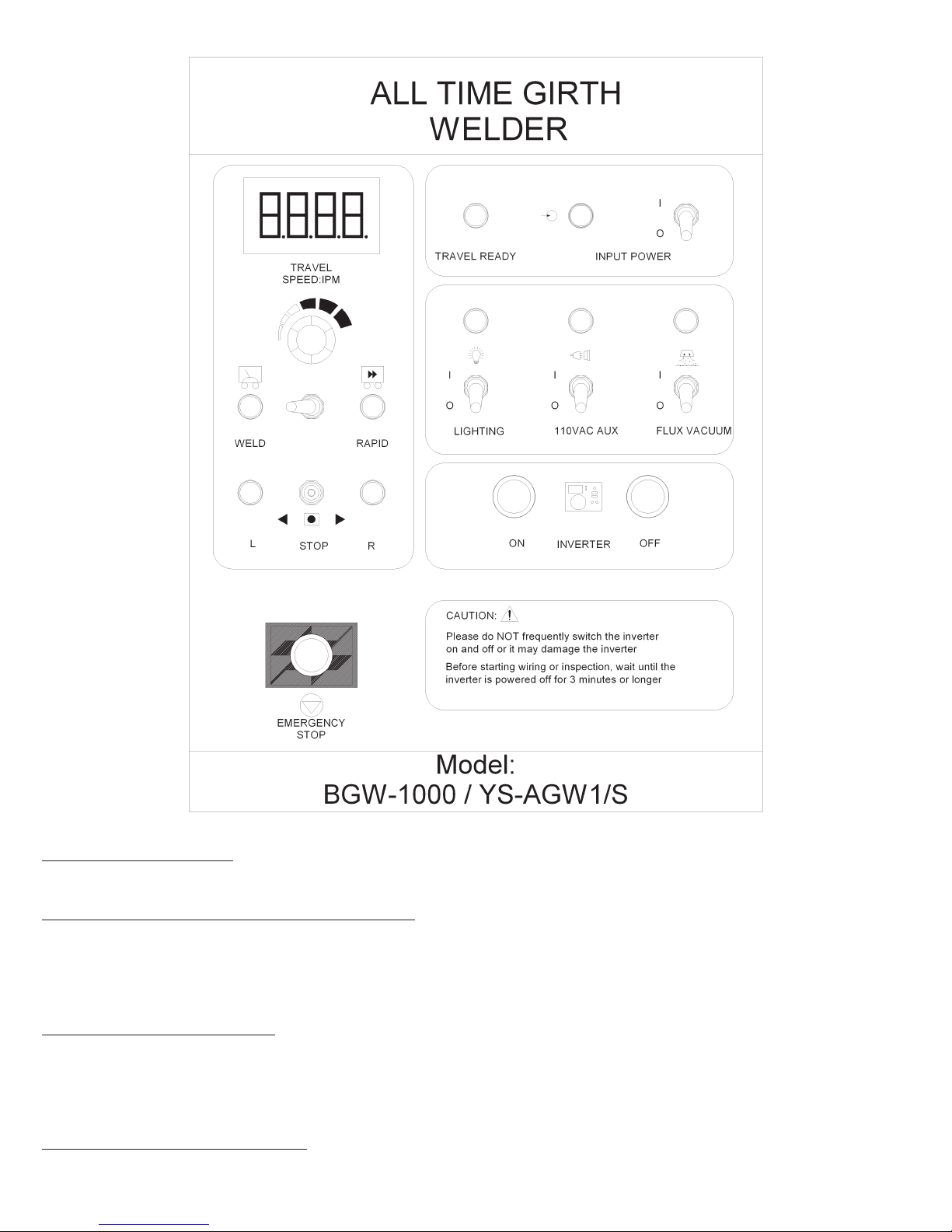
Master Control
The BGW master control houses the electronic travel inverter drive
and associated control relays; it provides a mean of integrated control
of all the accessories of the girth welder (eg. flux vacuum, 220V single
phase aux outlet, lamp, flux winch).
The control panel includes all necessary control knobs and switches
such as the speed control potentiometer, direction switch, full speed
travel switch as well as emergency stop button.
110VAux Version Control System
The Bug-oAll Time BGW sold in the markets using 110V are equipped
withaspecial circuitrytoprovide 110V auxoutletand lamps.The 110V
outlet socket is identified with yellow color instead of blue as in the
standard 220V aux power outlet.

8
“Power source switch”
Turns on the main power of the control.
“Left-Stop-Right” travel direction switch (S1)
Placing the switch in the selected side causes the machine to move in that particular welding direction.
For automatic travel, the travel switch on the NA3 must be in the travel position. To operate manually,
the switch must be in the hand position.
“Speed potentiometer” (R1)
Accurately adjust speed travel speeds (cm/min) of the girth welder. The speed can be monitored at the
control display.
U.S. version of Bug-oAll Time BGW would be programmed to display travel speed in IPM (inch per minute).
Normal / full speed travel switch
Activate girth welder full speed travel when the welding equipment is set to “manual” mode or “off”.

9
“Flux recovery vacuum” switch (S2)
Turns on the power of the vacuum for flux recovery.
Inverter ON/OFF “Lighting switch”
Push button switches to power on / off the inverter. Switch on the hurricane lamp for night operation.
CAUTION: Switching the inverter on and off in Emergency stop short interval could cause damage to
the inverter. It is not recommended to switch on the inverter again for at least three minutes after is it
turned off.
“Lighting switch”
Switch on the hurricane lamp for night operation.
Emergency Stop
Push button stops all electronic functions including welding and travel.
Slave Control (for BGWII double sided model ONLY)
Used at the slave side of the double sided girth welder, it is basically the same as the master control, but without
the function to control the drive system.

10
Flux Recovery
The welding head assembly includes a flux belt mechanism for necessary flux recycling.
The flux belt is made of a heat resistant latex belt that can tolerate up to
250 degree C (480 F) of heat. The belt is mounted on two 6'' (150mm)
diameter rollers, which can be adjusted and positioned by the flux belt
assembly hand wheel.
Thewelding fluxthat fallson the
fluxbeltis extracted bythe suc-
tion hose and is returned to the
flux hopper 176 lbs. (80kg ca-
pacity)mountedontheplatform.
The suction force is created by a 1400W cylindrical vacuum.Amanual
valve is applied between the vacuum and flux recovery system for
necessary vacuum force adjustment.
Heavy Duty Blower Type Vacuum / Filter System
(OPTIONAL)
The Bug-o All Time BGW may be equipped with a heavy duty blower
type vacuum for multi shifts continuous operation. Such vacuum sys-
tems can be configured as follows to suitable various operation re-
quirements:
(a) Separator / Filter mounted on top of the operator platform.
(b) Separator / Filter mounted on frame roof (vacuum system would
move upward along with the roof and drive section of the BGW).
Electrical Cabinet & Power Supply Storage.
The electrical cabinet of the girth welder is inside the power source
storage. It consists of a main circuit breaker at the left to receive the
local 3 phase input (380V / 3ph/ 60Hz as standard) and distribute it to
the power supply and the step down transformer, which in turn steps
down the voltage to 220VAC single phase to the secondary circuit
breaker.
The single phase 220VAC is required by the master control and all
electrical accessories supported by the girth welder.
Flux Recovery System
Flux Feed Nozzle
Small Hopper
Flux Feed Hose
FluxFlowValve
Flux Belt
Flux
Pickup
Nozzle
Must be
Sealed
Flux
Hopper Vent VentVacuum
Dieses Handbuch passt für folgende Modelle
1
Inhaltsverzeichnis
Andere BUG-O Schweißsystem Handbücher
Beliebte Schweißsystem Handbücher anderer Marken

TAFA
TAFA 30*8B35 Bedienungsanleitung

Lincoln Electric
Lincoln Electric INVERTEC V350-PRO CE Bedienungsanleitung

ESAB
ESAB Buddy Arc 145 Bedienungsanleitung

CIGWELD
CIGWELD 636804 Kurzanleitung

Red-D-Arc
Red-D-Arc DC-400 Bedienungsanleitung

Hobart Welding Products
Hobart Welding Products Spool Gun DP 3035-10 Bedienungsanleitung