
BVA Hydraulics HC1201T Bedienungsanleitung

Printed in Taiwan
This is the safety alert symbol. It is used to alert you to potential personal injury hazards.
Obey all safety messages that follow this symbol to avoid possible injury or death.
!
HC1201T-M0_032016_EN-FR-ES
Maximum Operating Pressure 10,000 PSI
Single Acting,
Hollow Hole Cylinders
Service Parts
SFA Companies 10939 N. Pomona Ave. Kansas City, MO 64153
Tel: 888-332-6419 * Fax: 816-448-2142
MODELS: HC1201T, HC1202T, HC1202XT, HC1203XT - 12 Ton Capacity
HC2002T, HC2006T - 20 Ton Capacity
HC3002T, HC3006T - 30 Ton Capacity
HC6003T, HC6006T - 60 Ton Capacity
HC10003T - 100 Ton capacity
2
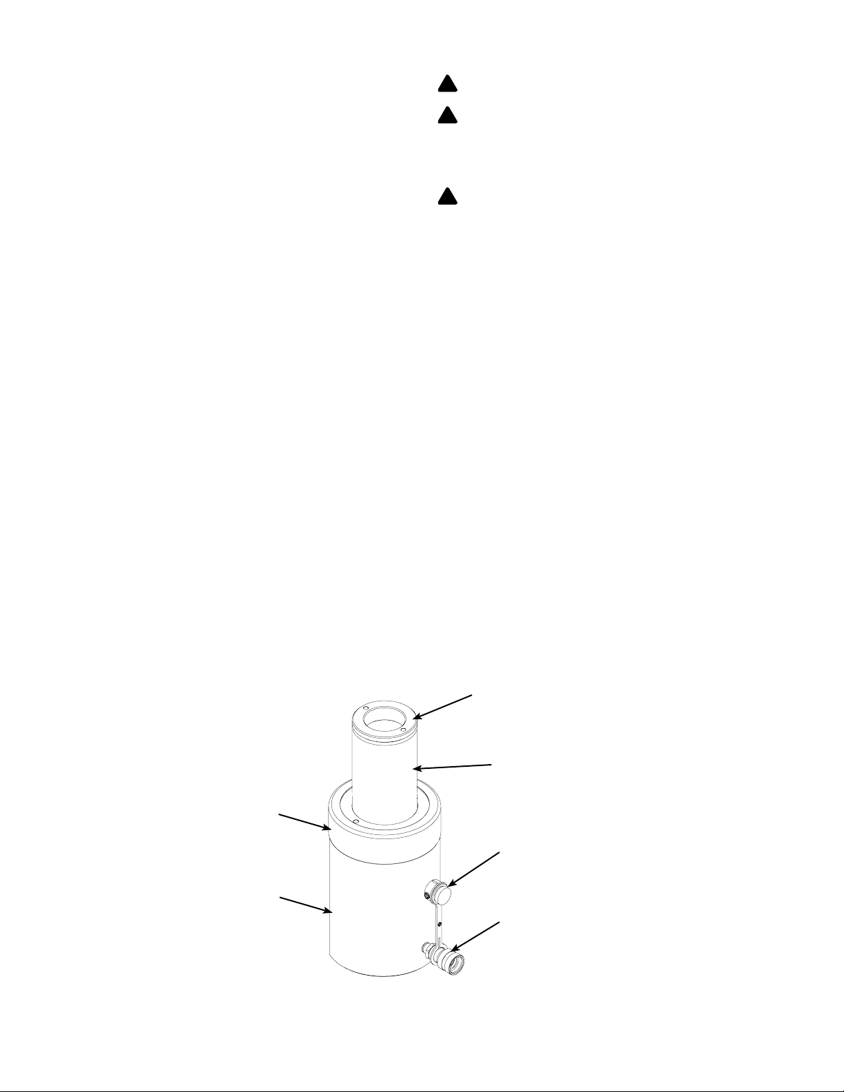
Figure 1 - Typical Cylinder Components
Collar
Protective Cap
Female Coupler, 3/8 NPTF
(HC12 series come with 1/4
NPTF coupler)
Dust Cap
Saddle
(HC1201, HC1202 & HC1203
do not have saddle)
Ram
Cylinder
SAFETY AND GENERAL INFORMATION
Save these instructions. For your safety, read and understand the
information contained within. The owner and operator shall have an
understanding of this product and safe operating procedures before
attempting to use this product. Instructions and safety information
shall be conveyed in the operator’s native language before use of
this product is authorized. Make certain that the operator thoroughly
understands the inherent dangers associated with the use and
misuse of the product. If any doubt exists as to the safe and proper
use of this product as outlined in this factory authorized manual,
remove from service immediately.
Inspect before each use. Do not use if leaking, broken, bent,
cracked or otherwise damaged parts are noted. If the cylinder has
been or suspected to have been subjected to a shock load (a load
dropped suddenly, unexpectedly upon it), discontinue use until
checked out by a BVA Hydraulics authorized service center. Owners
and operators of this equipment shall be aware that the use and
subsequent repair of this equipment may require special training
and knowledge. It is recommended that an annual inspection be
done by qualied personnel and that any missing or damaged
parts, decals, warning/safety labels or signs be replaced with BVA
Hydraulics authorized replacement parts only. Any cylinder that
appears to be damaged in any way, is worn or operates abnormally
shall be removed from service immediately until such time as repairs
can be made.
PRODUCT DESCRIPTION
BVA Hydraulics Single Acting Hollow Hole Cylinder is designed
for rated capacity pushing, spreading and pressing jobs. A wide
variety of applications exist for this category of product. Special
skill, knowledge and training may be required for a specic task
and the product may not be suitable for all the jobs described
above. Unsuitable applications would include applications that call
for a device to move, level or support persons, animals, hazardous
materials, mobile homes/dwellings in general, mirrors and/or plate
glass, and/or to connect/secure hatches, components, etc. between
bulkheads. The user ultimately must make the decision regarding
suitability of the product for any given task and therefore accept
responsibility for that decision. Immediately after lifting, loads must
be supported by appropriate mechanical means.
WARNING: NEVER use hydraulic cylinder as a
support device.
WARNING: Always check connections before using.
Alteration of these products is strictly prohibited. Use only
those adapters and attachments provided and approved by
the manufacturer.
WARNING: To reduce the risk of personal injury and/or
property damage, ensure that the rated working pressure of
each pressurized attachment be equal to or greater than the
rated working pressure developed by the hydraulic pump.
BEFORE USE
1. Before using this product, read the owner's manual completely
and familiarize yourself thoroughly with the product, its
components and recognize the hazards associated with its use.
2. Verify that the product and the application are compatible. If in
doubt, call BVA Hydraulics Technical Service (888) 332-6419.
3. Inspect before each use. Do not use if bent, broken, leaking or
damaged components are noted.
4.
Replace worn or damaged parts and assemblies with BVA
Hydraulics authorized replacement parts only. Lubricate as
instructed in Maintenance Section.
5. Ensure method of conrming load is accurate and working
properly. Have gauge or load cell accuracy veried by qualied
personnel on a yearly basis.
!
!
!

3
Failure to comply with the following warnings may
result in personal injury as well as property
damage.
• Study, understand, and follow all instructions
provided with and on this device before use.
• Theusermustbeaqualiedoperatorfamiliarwith
the correct operation, maintenance, and use of cylinders.
Wear protective gear when operating
hydraulic equipment.
This device is NOT suitable for use as support
device! As the load is lifted, use blocking and cribbing
to guard against a falling load. Stay clear of a lifted
load before it is properly supported. Never rely on
hydraulic pressure to support a load.
Crush Hazard. Keep hands and feet away
from cylinder and workpiece during
operation.
• Do not exceed rated capacity of the cylinder or
any equipment in the system. The cylinder is
designed for a max. pressure of 10,000 psi.
• Do not connect a cylinder to a pump with higher pressure rating.
• Do not subject cylinder to a shock loads, a load dropped
suddenly, causing the system pressure to exceed rated
pressure.
The system operating pressure must not exceed the
pressure rating of the lowest rated component
the system. Install a pressure gauge or other load
measuring instrument to monitor the operating pressure. Burst
hazard exists if hose, connection or any other component in the
system exceed its rated pressure.
Avoid damaging hydraulic hose. Do not allow hose
to kink, twist, curl, crush, cut or bend so tightly that
uid ow within the hose is blocked or reduced.
Periodically inspect the hose for wear.
Do not pull, position or move cylinder setup by the
hose. Use carrying handle or other means of safe
transport.
Do not handle pressurized hoses. Never attempt to
grasp a leaking pressurized hose. Ensure to release
the system pressure before disconnecting hydraulic
hose or connections.
Hydraulic uid can ignite and burn. Keep
hydraulic
equipment away from ames and heat.
Excessive
heat will soften seals, resulting in uid leaks. Heat
also weakens hose materials.
Cylinder must be on a stable base which is able
to support the load while pushing or lifting. Use shims,
friction material or constrains to prevent slippage
of the base or load. Ensure cylinder is fully engaged
into/onto adapters, extension accessories.
Center load on cylinder. Distribute load evenly across
the entire saddle surface. Do not off-center loads on
a cylinder. The load can tip or the cylinder can
“kick out”.
Never try to disassemble a hydraulic cylinder, refer
repairstoqualied,authorizedpersonal.ContactBVA
Hydraulics tech service for authorized service center.
Do not subject hose to sharp objects or heavy
impact.
Hose material or seals must not come in contact with
corrosive materials such as battery acid, creosote-
impregnated objects and wet paint. Never paint a
coupler or hose.
•
No alteration shall be made to the cylinder.
•
Use only factory authorized fasteners, accessories
andhydraulicuid.
!WARNING
Heavy
INSTALLATION
NOTICE: Use an approved, high-grade pipe sealant to seal all
hydraulic connections.
1.
Remove the dust cover and rubber plug from coupler
.
2. Inspectallthreadsandttingsforsignsofwearordamage,and
replaceasneeded.Cleanallthreadsandttings.
3. Connect hydraulic hose from hydraulic pump to the cylinder
coupler.Ensurethattherearenouidleaks.
4. Install in-line pressure gauge.
5. Check for leaks in system and have repaired by qualified
personnel.
NOTICE: The use of cylinder attachments or extensions reduces
the cylinder capacity by at least 50% per attachment/extension.
WARNING: Before operating the pump, tighten all hose
connections with proper tools. Do not overtighten. Connections
should only be tightened securely and leak-free. Overtightening can
cause premature thread failure or high pressure ttings to burst.
WARNING: Before repairs are made, depressurize cylinder.
Tipsforhydraulichoses&uidtransmissionlines:
• Avoid short runs of straight line tubing. Straight line runs do not
provide for expansion and contraction due to pressure and/or
temperature changes.
• Reduce stress in tube lines. Long tubing runs should be
supported by brackets or clips.
!
!

4
OPERATION
Operate the hydraulic pump to advance and retract the cylinder.
Do not continue pumping when cylinder is fully extended. Internal
pressure will build up and may damage the seal of the cylinder.
WARNING: NEVER rely on hydraulic pressure alone to
secure a load! NEVER allow personnel to work or pass under
a load until the load is secured by cribbing, blocking, or other
mechanical means.
WARNING: To help prevent material fatigue if the cylinder
is to be used in a continuous application, the load should not
exceed 85% of the rated capacity.
WARNING:
Your cylinder, hose(s), couplings and pump all must
be rated for the same maximum operating pressure, correctly
connected and compatible with the hydraulic uid used. An
improperly matched system can cause the system to fail.
WARNING: All personnel must be clear before lowering load.
MAINTENANCE
1. Inspect hoses and connections daily. Replace damaged
components immediately with BVA Hydraulics Replacement
Parts only.
2. Tighten connections as needed. Use pipe thread sealing
compound when servicing connections.
3. Alwaysuse clean, approvedhydraulic uid and change as
recommended or sooner if the uid becomes contaminated
(never exceed 400 hours). Follow pump manufacturers
instructionsforchangingandaddinghydraulicuid.Useonly
good quality hydraulic uid. We recommend Mobil DTE13M
or equivalent when using with hand pump or air pump; BVA
Hydraulics Oil (F01) or equivalent when using with electric pump.
Neverusebrakeuid,transmissionuid,turbineoil,motoroil,
alcohol, glycerin etc. Use of other than good quality hydraulic
oil will void warranty and damage the cylinder, pump, hose etc.
4. Use an approved, high-grade pipe thread sealant to seal all
hydraulicconnections.Teontapecanbeusedifonlyonelayer
of tape is used and it is applied carefully (two threads back) to
prevent the tape from being introduced into hydraulic system. A
piece of tape could travel through the system and obstruct the
owofuidandadverselyaffectfunction.
Lubrication & Cleaning
Keep cylinder clean at all times.
1. Any exposed threads (male or female) must be cleaned and
lubricated regularly, and protected from damage. Lubricate with
light machine oil.
2. If a cylinder or ram has been exposed to rain, snow, sand,
airborne abrasive, or any corrosive environment, it must be
cleaned, lubricated, and protected immediately after exposure.
Dailycleanexposedramwithcleanclothdampenedwithlight
machine oil. Protect exposed ram from the elements at all times.
3. Keepthehydraulic system as freeofdirtaspossible. When
not in use, couplers must be sealed with dust covers. All hose
connections must be free of dirt and grime. Any equipment
attached to the cylinder must be kept clean.
Storage
Cylinders should be stored vertically with ram plunger fully retracted
in a dry, protected area, not exposed to corrosive vapor, dust or
otherharmfulelements.Whenacylinderhasnotbeenusedfor
a period of 4 months, it should be connected to a pump and fully
extended and then retracted a minimum of 5 times. This cycle will
lubricate the cylinder wall, reducing the possibility of corrosion and
damage thereof.
How to remove faulty coupler:
If cylinder does not retract,
1. Secure load by other means.
2. Depressurizepumpandhose.
3. Remove the cylinder from application.
4. Disconnectandreplacewithnewcoupler.
!
!
!
!
SPECIFICATIONS
Model
Number
Cylinder
Capacity
(tons)
Stroke
(in)
Cylinder
Effective
Area (in
2
)
Internal
Pressure at
Capacity (psi)
Oil
Capacity
(in
3
)
Collapsed
Height
(in)
Extended
Height
(in)
Weight
(lbs)
Cylinder
Housing
Dia. (in)
Collar
Thread
Mounting
Hole Dia.
HC1201T
12
0.31
2.91 8,236
0.89 2.36 2.67 3.3
2.76 23/4”-16 2.00
HC1202T 1.61 4.70 4.74 6.36 6.2
HC1202XT 1.61 4.70 4.74 6.36 6.2
HC1203XT 2.99 8.72 7.24 10.24 8.6
HC2002T 20 2.01 4.90 8,167 9.83 6.38 8.39 15.9 3.92 37/8”-12 3.25
HC2006T 6.06 29.70 12.05 18.11 29.5
HC3002T 30 2.52 6.32 9,488 15.93 7.05 9.57 22.9 4.50 41/2”-12 3.62
HC3006T 6.11 38.67 13.02 19.13 43.0
HC6003T 60 3.00 13.05 9,195 39.10 9.77 12.77 65.7 6.25 61/4”-12 5.12
HC6006T 6.00 78.25 12.76 18.76 81.1
HC10003T 100 3.00 22.13 9,036 66.31 10.00 13.00 113.3 5.31 83/8”-12 7.01

5
TROUBLESHOOTING GUIDE
The following information is intended as an aid in determining if problem exists. Cylinders should be repaired only by authorized BVA
Service Center. For repair service, contact service center in your area.
Symptom Possible Causes Corrective Action
Erratic action
•
Air in system or pump cavitation.
• External leakage in cylinder.
• Cylinder sticking or binding.
•Ventthesystem(refertogure2).
• Contact service center.
• Contact service center.
Cylinder will not extend, or
respondtopressurizeduid
•
Overload condition.
• Loose couplers.
• Faulty couplers.
• Improper valve position.
• Oil level in pump is low.
• Pump not operating.
• Air-locked pump.
• Remedy overload condition.
• Tighten couplers.
• Replace both female and male couplers.
• Close release valve or change valve position.
• Fill and bleed the system.
• Check pump’s operating instructions.
• Prime pump per pump operating instructions.
Cylinder extend only partially
• Oil level in pump is low.
•
Overload condition.
• Cylinder is sticking or binding.
• Fill and bleed the system.
• Remedy overload condition.
• Contact service center.
Cylinder move slower than normal
• Loose connection or coupler.
•
Restrictedhydrauliclineortting.
• Pump not working correctly.
• Cylinder seals leaking.
• Tighten connection or coupler.
• Clean and replace if damaged.
• Check pump’s operating instructions.
• Contact service center.
Cylinder responds to pressurized
uid,butsystemdoesnotmaintain
pressure
• Overload condition.
• Pump or valve malfunctioning.
• Cylinder seals leaking.
• Remedy overload condition.
• Check pump’s operating instructions.
• Contact service center.
Oil leaking from cylinder • Worn or damaged seals. • Contact service center.
Cylinder will not retract or retracts
slower than normal
• Improper valve position.
• Malfunctioning coupler, damaged
application.
•Pumpreservoiroverlled.
• Cylinder damage internally.
• Open release valve or change valve position.
• Secure load by other means. Depressurize
pump and hoses, remove application and
replace coupler.
• Secure load by other means. Depressurize
pump and hoses, remove application, then drain
uidtoproperlevel.
• Contact service center.
Cylinder performs poorly • Oil level in pump is low.
• Air trapped in system.
• Ensure proper oil level.
•Ventthesystem(refertogure2).
Figure2-Illustrationtobleedairfromsystem
MAINTENANCE (cont.)
NOTICE: Do not attempt to grasp with pliers or wrench without
rst wrapping the jaws of such tool with rags or similar padding.
How to bleed air from system:
1. Place pump at a higher elevation than the hose and cylinder
asshowninFigure2.
2. Operatepumptofullyextendandretractthecylinder2or3times.
The objective is to force the air bubbles up hill and back to the
pump reservoir.
3. Followpumpinstructionmanualtobleedtheairfrompump
reservoir. On most pumps, air can escape by opening the oil
llerplug/screw.

6
Item
Part Number for Model:
Description Qty
HC1201T
1 N/A Cylinder 1
2 N/A Center Tube 1
3 N/A Plunger 1
4 * Back-Up Ring 1
5 * O-Ring 1
6 * O-Ring 1
7*Back-Up Ring 1
8 666-5-0300-107 C-Clip 1
9 CRZ14F Coupler, 1/4" 1
10 * O-Ring 1
11 * Back-Up Ring 1
12 *O-Ring 1
13 512-2-0460-104 Comp. Spring 1
14 H32-6-2305-100 Protecting Cap 1
15 H32-6-1821-103 Upper Bearing 1
16 * O-Ring 1
* H32-3-9906-103 Repair Kit 1
Single Acting,
Hollow Hole Cylinders
Service Parts
SFA Companies 10939 N. Pomona Ave. Kansas City, MO 64153
Tel: 888-332-6419 * Fax: 816-448-2142
MODELS: HC1201T
Note: Not all components of the pump are replacement items, but are illustrated as a convenient reference of location and
position in the assembly sequence.
Note: To ensure safe and reliable performance, replace worn or damaged parts with BVA Hydraulics Authorized
Replacement Parts only.
(*) - indicates items included in, and available only as part of Seal Kit
N/A - part is not available as replacement
13
4
5
3
12
11
10
14
15
16
1
9
6
7
2
8

Single Acting,
Hollow Hole Cylinders
Service Parts
SFA Companies 10939 N. Pomona Ave. Kansas City, MO 64153
Tel: 888-332-6419 * Fax: 816-448-2142
MODELS: HC1202T & HC1202XT
Note: Not all components of the pump are replacement items, but are illustrated as a convenient reference of location and
position in the assembly sequence.
7
8
2
9
15
4
5
3
6
14
13
12
11
1
10
17
18
16
Item
Part Number for Model:
Description Qty
HC1202T & HC1202XT
1 N/A Cylinder 1
2 N/A Center Tube 1
3 N/A N/A Plunger 1
4 * Back-Up Ring 1
5 * U-Cup 1
6 H32-6-1122-107 Bearing 1
7 * O-Ring 1
8 * Back-Up Ring 1
9 666-5-0300-107 C-Clip 1
10 CRZ14F Coupler, 1/4" 1
11 H32-6-1121-105 Bearing 1
12 * U-Cup 1
13 * Back-Up Ring 1
14 * O-Ring 1
15 512-2-0470-107 Comp. Spring 1
16 H32-6-2305-100 Protecting Cap 1
17 H32-6-1821-103 Upper Bearing 1
18 * O-Ring 1
* H32-3-9905-101 Repair Kit 1
Note: To ensure safe and reliable performance, replace worn or damaged parts with BVA Hydraulics Authorized
Replacement Parts only.
(*) - indicates items included in, and available only as part of Seal Kit
N/A - part is not available as replacement

8
20
1
2
3
11
12
13
14
15
16
17
4
5
6
18
7
8
9
10
19
Single Acting,
Hollow Hole Cylinders
Service Parts
SFA Companies 10939 N. Pomona Ave. Kansas City, MO 64153
Tel: 888-332-6419 * Fax: 816-448-2142
MODELS: HC1203XT, HC2002T, HC2006T, HC3002T & HC3006T (ref parts list pg 8)
Note: Not all components of the pump are replacement items, but are illustrated as a convenient reference of location and
position in the assembly sequence.

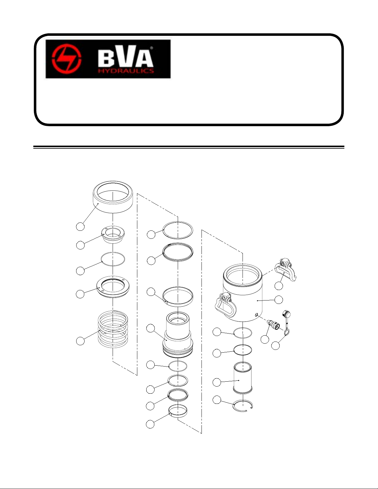
Item Part Number for Model: Description Qty
HC1203XT HC2002T HC2006T HC3002T HC3006T
1 H32-6-2305-100 H32-6-2306-102 H32-6-2307-104 Collar Protective
Cap
1
2 * O-ring 1
3 H32-6-1821-103 H32-6-1822-105 H32-6-1823-107 Upper Bearing 1
4 512-2-0490-103 512-2-0710-101 512-2-0740-100 512-2-0815-105 512-2-0835-101 Return Spring 1
5*Back-up Ring 1
6 * U-cup 1
7 N/A Ram 1
8 * O-ring 1
9 * Back-up Ring 1
10 * U-cup 1
11 N/A Cylinder 1
12 * O-ring 1
13 * Back-up Ring 1
14 N/A Center Tube 1
15 666-5-0300-107 666-5-0500-105 666-5-0550-100 C-clip 1
16 H02-4-6001-104 Female Coupler 1
17 H02-4-6003-108 H02-4-6003-108 H02-4-6003-108 Dust Cover 1
18 H32-6-1122-107 H32-6-1126-105
H32-6-1131-108 H32-6-1130-106
Bearing 1
19 H32-6-1121-105 H32-6-1125-103 H32-6-1129-101 Bearing 1
20 N/A H32-6-1103-204 H32-6-1104-206 Saddle 1
(*) H32-3-9905-101 H32-3-9902-105 H32-3-9901-103 Repair Kit -
9
Single Acting,
Hollow Hole Cylinders
Service Parts
SFA Companies 10939 N. Pomona Ave. Kansas City, MO 64153
Tel: 888-332-6419 * Fax: 816-448-2142
MODELS: HC1203XT, HC2002T, HC2006T, HC3002T & HC3006T (ref parts list pg 7)
Note: Not all components of the pump are replacement items, but are illustrated as a convenient reference of location and
position in the assembly sequence.
Note: To ensure safe and reliable performance, replace worn or damaged parts with BVA Hydraulics Authorized
Replacement Parts only.
(*) - indicates items included in, and available only as part of Seal Kit
N/A - part is not available as replacement
1
20
2
3
4
5
6
18
7
8
9
10
19
8
13
14
15
11
12
16
17
10
Single Acting,
Hollow Hole Cylinders
Service Parts
SFA Companies 10939 N. Pomona Ave. Kansas City, MO 64153
Tel: 888-332-6419 * Fax: 816-448-2142
MODEL: HC6003T, HC6006T & HC10003T (ref parts list on pg 10)
Note: Not all components of the pump are replacement items, but are illustrated as a convenient reference of location and
position in the assembly sequence.
Dieses Handbuch passt für folgende Modelle
10
Inhaltsverzeichnis
Sprachen:
Andere BVA Hydraulics Jack Handbücher

Beliebte Jack Handbücher anderer Marken


VEVOR
VEVOR TJD-12000SP-F Bedienungsanleitung

ULTIMATE SPEED
ULTIMATE SPEED URW 2 A1 HYDRAULIC TROLLEY JACK Bedienungsanleitung

Stels
Stels 51131 Bedienungsanleitung

Bushranger
Bushranger RJX01 Bedienungsanleitung

Clarke
Clarke CTJ2500QLG Installations- und Betriebshandbuch

Valex
Valex 1650520 Bedienungsanleitung


