
Cafe CDD220PXX Bedienungsanleitung
TM
WARNING
CAUTION
FOR YOUR SAFETY
Read and observe all WARNINGS and CAUTIONS shown throughout these
instructions.
IMPORTANT – Observe all governing codes and ordinances.
ŶNote to Installer – Be sure to leave these instructions for the consumer’s and
local inspector’s use.
ŶNote to Consumer – Keep these instructions with your Owner’s Manual for
future reference.
ŶSkill Level – Installation of this dishwasher requires basic mechanical, electrical
and plumbing skills. Proper installation is the responsibility of the installer.
Product failure due to improper installation is not covered under the GE
Appliances Warranty. See Warranty information.
ŶCompletion Time – 1 to 3 Hours. New installations require more time than
replacement installations.
IMPORTANT – The dishwasher MUST be installed to allow for future removal from
the enclosure if service is required.
Care should be exercised when the appliance is installed or removed, to reduce the
likelihood of damage to the power supply cord.
If you received a damaged dishwasher, you should immediately contact your dealer
or builder.
Your dishwasher is a water heating appliance.
BEFORE YOU BEGIN - Read these instructions completely and carefully.
ŶTo reduce the risk of electric shock, fire, or injury to persons, the installer must
ensure that the dishwasher is completely enclosed at the time of installation.
ŶFOR PERSONAL SAFETY: Remove house fuse or open circuit breaker before
beginning installation. Do not use an extension cord or adapter plug with this
appliance.
ŶThe improper connection of the equipment grounding conductor can result in a
risk of electric shock. Check with a qualified electrician or service representative
if you are in doubt that the appliance is properly grounded.
ŶIf house wiring is not 2-wire with ground, a ground must be provided by the installer.
When house wiring is aluminum, be sure to use UL-Listed anti-oxidant
compound and aluminum-to-copper connectors.
ŶTo reduce the risk of electric shock, fire, or injury to persons, the installer should
check to ensure that wires
are not pinched or damaged, the house wiring is attached
to the dishwasher through a strain relief, and
all electrical connections made at
the time of install
are contained inside of the terminal block cover.
ŶFor models equipped with power cord: Do not modify the plug provided
with the appliance; if it will not fit the outlet, have a proper outlet installed by a
qualified technician.
While performing installations described in this booklet, gloves, safety glasses
or goggles should be worn.
If you have questions, visit our website at: cafeappliances.com
Installation Instructions Dishwasher Drawer
READ CAREFULLY
KEEP THESE INSTRUCTIONS

2
Precauciones en Español
PARA SU SEGURIDAD
Lea y cumpla con todas las ADVERTENCIAS y PRECAUCIONES que figuran
en estas instrucciones.
IMPORTANTE – Cumpla con todos los códigos y ordenanzas gubernamentales.
ŶNota para el Instalador – Asegúrese de entregar estas instrucciones al consumidor
y al inspector local.
ŶNota para el Consumidor – Guarde estas instrucciones con su Manual del
Propietario para referencia futura.
ŶNivel de habilidad – La instalación de este lavavajillas requiere un nivel básico
de habilidades mecánicas, eléctricas y de plomería. La correcta instalación
del producto es responsabilidad del instalador. Si se producen fallas en el
producto debido a una instalación inadecuada, la Garantía del Producto de
GE Appliances no cubrirá las mismas. Consulte la información de la Garantía.
ŶTiempo de instalación – 1 y 3 Horas. Las instalaciones nuevas requieren más
tiempo que las instalaciones de reemplazo.
IMPORTANTE – El lavavajillas DEBE ser instalado para permitir el retiro futuro de
su ubicación, si se requiere realizar el servicio técnico.
Se deberá tener cuidado cuando el electrodoméstico sea instalado o retirado, a fin
de reducir la posibilidad de daños sobre el cable de suministro eléctrico.
Si el lavavajillas que recibió está dañado, se debería comunicar de inmediato con
su vendedor o fabricante.
Su lavavajillas es un electrodoméstico donde se calienta agua.
ANTES DE COMENZAR - Lea estas instrucciones en su totalidad y atentamente.
ŶPara reducir el riesgo de descarga eléctrica, incendio o lesiones a personas, el
instalador debe asegurarse de que el lavaplatos esté completamente cerrado en el
momento de la instalación.
ŶPARA SEGURIDAD PERSONAL: Quite el fusible o abra el interruptor de
circuitos antes de comenzar la instalación. No utilice un cable de extensión o un
enchufe adaptador con este artefacto.
ŶLa conexión inadecuada del conductor de conexión a tierra del equipamiento
puede provocar un riesgo de descarga eléctrica. Consulte a un electricista
FDOL¿FDGRRUHSUHVHQWDQWHGHVHUYLFLRWpFQLFRVLWLHQHGXGDVVREUHODFRUUHFWD
conexión a tierra del aparato.
Ŷ
Si el cableado doméstico no cuenta con un cable de 2 hilos con conexión a
tierra, un instalador debe realizar una conexión a tierra. Cuando el cableado
doméstico es de aluminio, asegúrese de usar un compuesto antioxidante y
conectores de aluminio a cobre aprobados por UL.
Ŷ
Para reducir el riesgo de descarga eléctrica, incendio o
lesiones a personas,
el instalador deberá realizar un
control para asegurar que los cables no estén
pellizcados
ni dañados, que el cableado del hogar esté conectado a la ficha de la caja
de empalmes a través de un amortiguador
de refuerzo, y que todas las conexiones
eléctricas
realizadas en el momento de la instalación (tuercas para
cables) estén
dentro de la tapa de la caja de empalmes.
Al realizar las instalaciones descritas en este folleto, se deben usar guantes,
gafas de seguridad o gafas protectoras.
ADVERTENCIA
PRECAUCIÓN
LEA DETENIDAMENTE
CONSERVE ESTAS INSTRUCCIONES
3
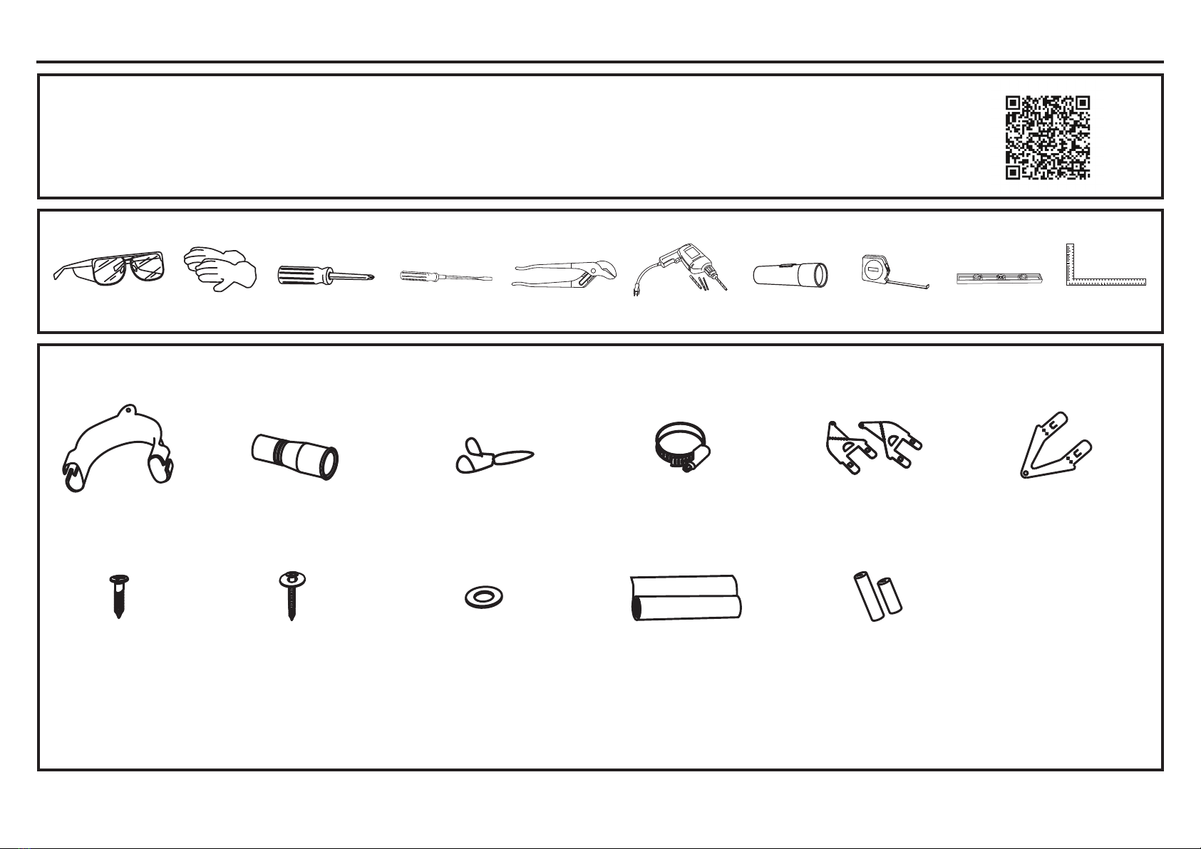
PARTS SUPPLIED IN
INSTALLATION PACKAGE
Installation Preparation
If the drain hoses supplied are not long enough to reach your services, you must use a Drain Hose Extension Kit WD24X30798 which will extend the drain hoses by 11’ 10” (3.6 m).
The kit is available from GEApplianceparts.com or by phone at 877.959.8688 during normal business hours.
Clamp (1)
(for securing
drain hose joiner)
Wire clip (2)
(for securing drain
hose joiner)
Phillips
»´PP
screws (7)
Drain hose
support (1)
Drain hose
joiner (1)
Top
mounting
brackets (2)
OPTIONAL
Side mounting
bracket kit
(A and B) (2)
OPTIONAL
NOTE: Consider recycling options for your appliance packaging material.
DISHWASHER DRAWER
INSTALLATION OVERVIEW
This video provides an overview of what is needed to install a Dishwasher Drawer.
It is intended as an overview only of the installation process and is not intended to be used as a guide on how to install the Dishwasher Drawer yourself.
TOOLS YOU WILL NEED
Measuring Tape
Phillips-Head
Screwdriver
Flashlight
Gloves Carpenter’s
Square
Safety Glasses Level
Flat Head
Screwdriver
Moisture protection
tape (1)
(to prevent moisture
damage to cabinetry)
Rubber washer
for inlet hose (1)
(comes already
fitted)
Hexagonal
socket for feet
adjustment (2)
(long & short)
1-1/2” (38 mm)
bottom fixing
screws & metal
washers (2)
Pliers
(Channel Lock)
Drill and Bits
4
Installation Preparation
FOR PERSONAL SAFETY: Remove house fuse or open circuit breaker before
beginning installation.
Do not use an extension cord or adapter plug with this appliance.
WARNING
The improper connection of the equipment grounding conductor can result in a risk
of electric shock. Check with a qualified electrician or service representative if you
are in doubt that the appliance is properly grounded.
WARNING
PREPARE ELECTRICAL WIRING
ELECTRICAL REQUIREMENTS
Be sure that the electrical connection and wire size are adequate and in conformance
with the National Electric Code, ANSI/NFPA 70 – latest edition, and all local codes
and ordinances.
This appliance must have:
• 120V, 60Hz, AC-only, 15-ampere or 20-ampere, fused electrical supply.
• Wiring must be 2 wire with ground and rated for 75°C (167°F).
• If the electrical supply does not meet the above requirements, call a licensed
electrician before proceeding.
It is recommended to have:
• A circuit breaker or time-delay fuse.
• A properly grounded individual branch circuit.
Grounding Instructions–Permanent Connection
This appliance must be connected to a grounded metal, permanent wiring system,
or an equipment-grounding conductor must be run with the circuit conductors and be
connected to the equipment-grounding terminal or lead on the appliance.
Grounding Instructions–Power Cord Models
This appliance must be grounded. In the event of a malfunction or breakdown,
grounding will reduce the risk of electric shock by providing a path of least resistance
for electric current. This appliance is equipped with a cord having an equipment-
grounding conductor and a grounding plug. The plug must be plugged into an
appropriate outlet that is installed and grounded in accordance with all local codes
and ordinances.
For models equipped with power cord: Do not modify the plug provided with
the appliance; if it will not fit the outlet, have a proper outlet installed by a qualified
technician.
WARNING
La conexión inadecuada del conductor de conexión a tierra del equipamiento puede
SURYRFDUXQULHVJRGHGHVFDUJDHOpFWULFD&RQVXOWHDXQHOHFWULFLVWDFDOL¿FDGRR
representante de servicio técnico si tiene dudas sobre la correcta conexión a tierra
del aparato.
ADVERTENCIA
Con los modelos equipados con cable de corriente: No modifique el enchufe
provisto con el electrodoméstico; si no coincide con el tomacorriente, solicite la
instalación de un tomacorriente apropiado a un electricista calificado.
ADVERTENCIA
PARA SEGURIDAD PERSONAL: Quite el fusible o abra el interruptor de circuitos
antes de comenzar la instalación. No utilice un cable de extensión o un enchufe
adaptador con este artefacto.
ADVERTENCIA
5
Installation Preparation
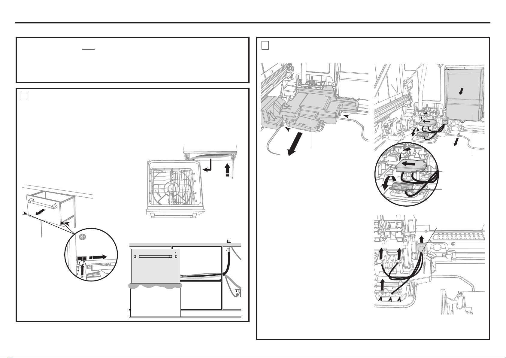
OPTIONAL - HARD WIRING PRIOR TO INSTALLATION
Access cover
Clip
Clip
1 With a flat-bladed screwdriver, push
in the clips and slide out the access
cover.
2 Unscrew the electronics module
cover.
3 Carefully pull out the electronics
module and rest on the chassis base
out of the way.
4 With a screwdriver, unclip the plastic
harness cover and hinge open.
5 Slide the terminal block cover
sideways to unlock and hinge open
to access the terminal block.
6 Unscrew the Live, Neutral and
Ground wires as shown.
NOTE: Only unscrew the live and
neutral terminals 2 turns. They are
fork terminals and do not require the
screws to be removed. The ground
requires the screw be removed. It is
a ring terminal. Remove the center
ground screw.
7 Unscrew the three screws on the
base as shown and remove the cord
from the product.
1
1
Remove existing
power cord
6
7
7
2
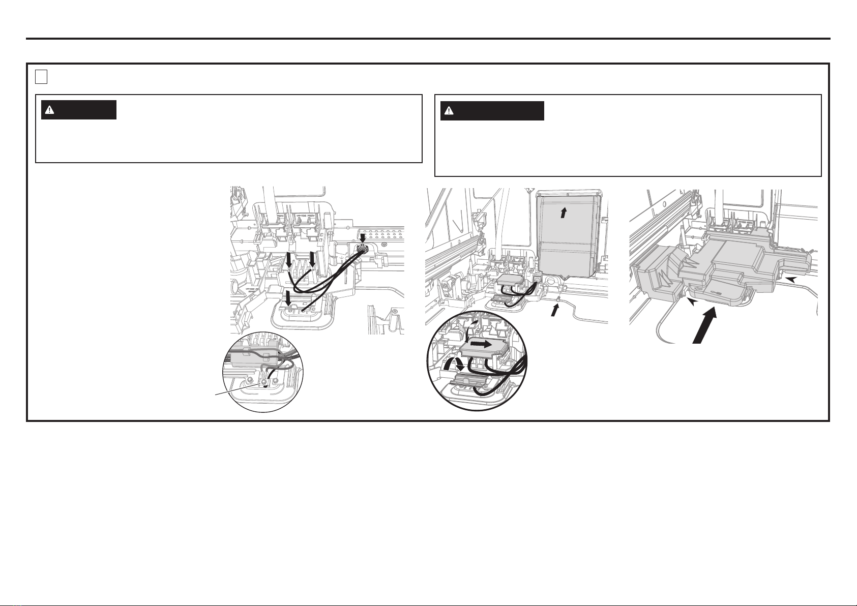
REMOVE THE ACCESS COVER AND REMOVE THE
POWER CORD (Skip step if using the power cord.)
Electronics
module
Terminal
block cover
2
3
4
5
Harness cover
POWER CORD OR HARDWIRE OPTION
We recommend the use of the power cord. If using the power cord option, skip steps 1-4 and
proceed to the PRODUCT DIMENSIONS section of this Installation Instructions.
If however you elect to hardwire the dishwasher drawer, follow steps 1-4 and then continue
with the rest of the Installation Instructions.
Lift the drawer off its runners and carefully
place it upright on the covered sturdy box
you had previously positioned nearby.
Press the release tabs in on both
sides and push them back to release
drawer from its runners.
In preparation of removing the
dishwasher drawer, so as to not strain
its rear connectors, place a sturdy box
near the installation site to rest the
drawer on after it is removed. Cover the
box with a towel to provide a protective
surface for the drawer to rest on.
Pull the dishwasher drawer out until it
stops.
1
2
4” (100 mm)
4
Push drawer
runners back
in on both
sides
Remove drawer*
Place on covered
sturdy box
3
*Do not move or rest the drawer too far to
prevent strain on its rear connectors.
5
Drawer resting
on covered
sturdy box
Rear
Connectors
1
REMOVE THE DISHWASHER DRAWER
(Skip step if using the power cord.)
6
Installation Preparation
OPTIONAL - HARD WIRING PRIOR TO INSTALLATION - CONTINUED
IMPORTANT: Ensure
house wires are routed
UNDERNEATH all other
harness wiring from the
electronics module.
8
9
10
11
12
13
14
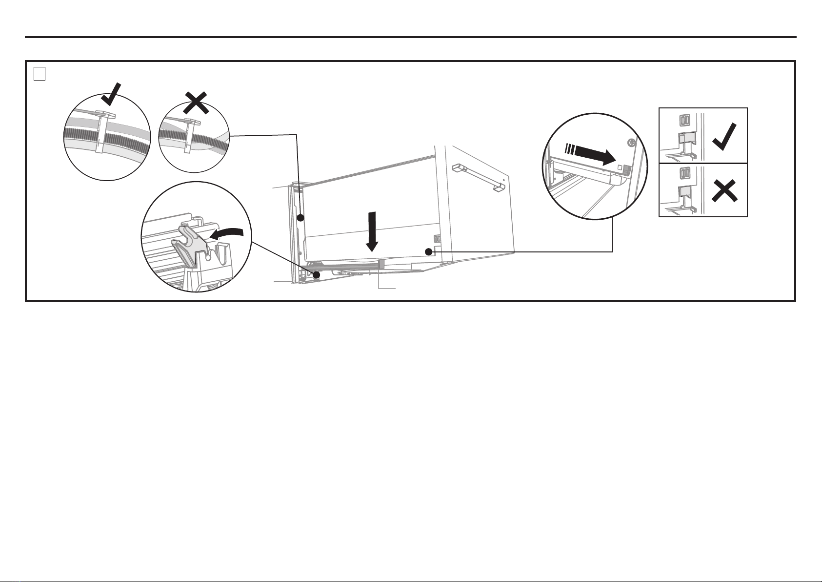
3TERMINATE HOUSE WIRING AS SHOWN AND REPLACE MODULE AND COVERS (Skip step if using the power cord.)
8 Fit a suitable cable clamp for the
conduit through the metal knockout.
Ensure wiring is routed through or
under housing ribs.
9 Screw down the Live, Neutral and
Ground wires correctly.
10 Push the plastic harness cover back
over. It should clip back into place
11 Fold down and slide back the
terminal block cover.
12 Refit the electronics module back
into position, being careful of wiring.
13 Replace the screw securing the
electronics module.
14 Slide the access cover back,
ensuring the 2 clips shown are fully
locked in place.
NOTE: Use copper conductors only.
9
IMPORTANT: Both ring terminals must be
replaced and the bare Ground wire clamped
If house wiring is not 2-wire with ground, a ground must be provided by the installer.
When house wiring is aluminum, be sure to use UL-Listed anti-oxidant compound
and aluminum-to-copper connectors.
WARNING
Si el cableado doméstico no cuenta con un cable de 2 hilos con conexión a tierra,
un instalador debe realizar una conexión a tierra. Cuando el cableado doméstico
es de aluminio, asegúrese de usar un compuesto antioxidante y conectores de
aluminio a cobre aprobados or UL.
ADVERTENCIA
7
Installation Preparation
OPTIONAL - HARD WIRING PRIOR TO INSTALLATION - CONTINUED
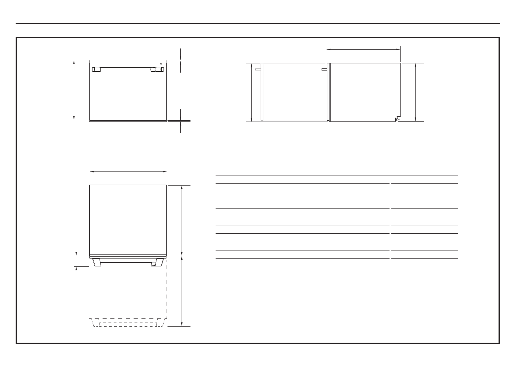
4” (100 mm)
Pull the release tabs forward on both
sides 4” (100 mm). Ensure the tabs are
fully pulled forward and click into place.
Before refitting the drawer,
ensure the hoses are not
twisted and the latches at
the rear of each drawer
runner are facing
forward.
Lift or rotate counter-clockwise the
drawer back onto the drawer runners
on either side.
Release tab
4REFIT THE DRAWER ONTO THE RUNNERS AND CLOSE (Skip step if using the power cord.)
1
2
3
4
8
PLAN
SIDEFRONT
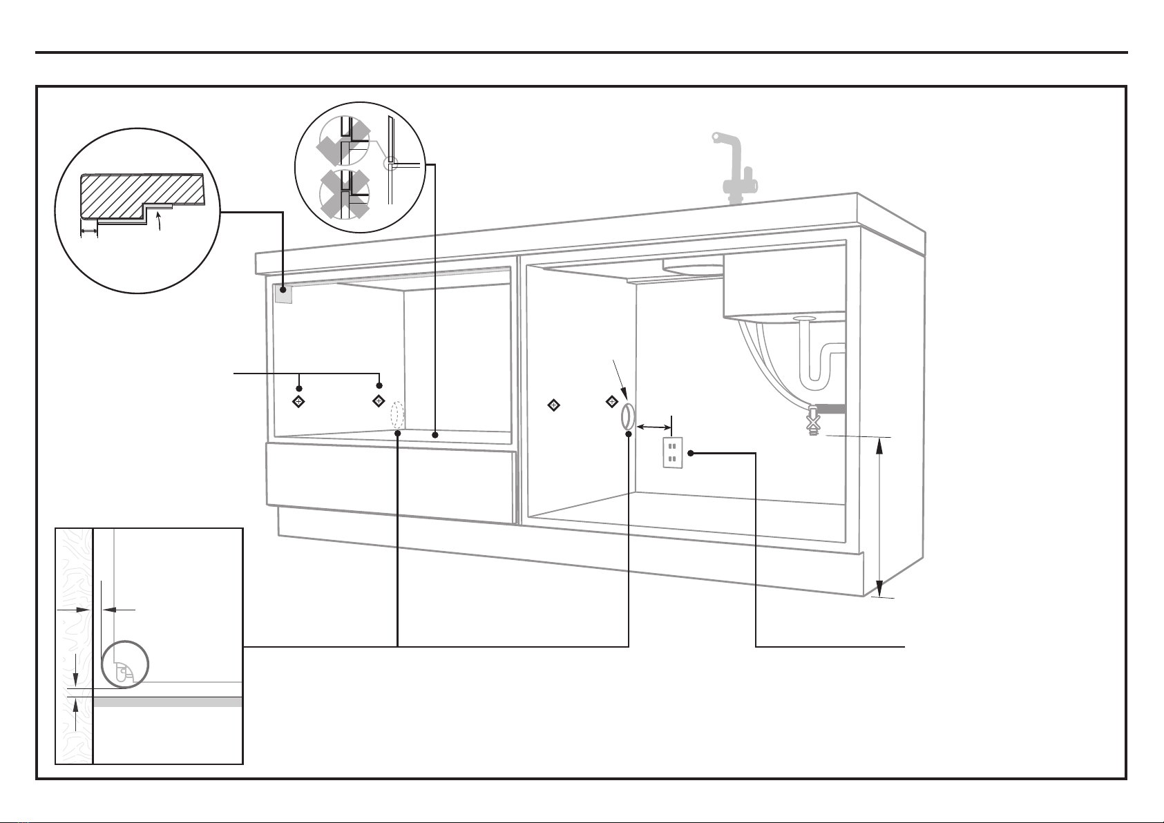
PRODUCT DIMENSIONS INCHES (MM)
A Overall height of product* 17-13/16” (453)
B Overall width of product 23-9/16” (599)
C Overall depth of product (excluding handle) 22-9/16” (573)
D Depth of chassis (to back of front drawer panel) 21-3/4” (553)
E Depth of drawer front panel (including handle) 3-7/16” (88)
F Height of drawer front panel 17-3/8” (442)
G Height of chassis 117-13/16” (453)
H Height from top of drawer front panel to top of chassis 1/8” (3)
I Ventilation gap between drawer front panels 5/16” (8)
J Maximum extension of drawer 22-3/4” (578)
*Includes 1/16” (2 mm) high bracket slots
PRODUCT DIMENSIONS
Installation Preparation
H
I
FG
C
A
B
D
J
E

9
Minimum clearances from adjacent cabinetry
Bracket slots
M
L
SIDE
PLAN
Min. 1/2” (13 mm)
clearance from a
corner cabinet
Min. 1/16” (2 mm)
clearance to adjacent
cabinet door
Installation Preparation
CABINETRY DIMENSIONS
CABINETRY DIMENSIONS INCHES (MM)
K Inside height of cavity* Min. 17-15/16” (456)
L Inside width of cavity 23-5/8” (600)
M Inside depth of cavity Min. 22-13/16” (580)
K
10
Water Connection
Recommended HOT
(Maximum 140°F/60°C).
Supplied hose to
VXLW»´PPPDOH
compression fitting.
Water Pressure
Max. 1 MPa (145 psi)
Min. 0.03 MPa (4.3 psi)
IMPORTANT
The power outlet must be
located in a cabinet adjacent
to the dishwasher cavity.
110-120 VAC max. 15 A
Service Hole
Can be located on either side of dishwasher, close to the rear face and the
shelf, as illustrated.
ŶIf the hole is through wood, make sure its edges are smooth and rounded.
These marks indicate formed
bracket screw locations, if
securing by drawer removal.
If there is no side partition, you
can construct timber bracing as
something to secure into.
Moisture
protection
tape must be
applied.
3/8”
(10 mm)
COUNTERTOP
IMPORTANT
Incorrect placement of the
hole will result in damage to
hoses.
Ø 1-1/2”
(38 mm)
Max. 17-11/16”
(450 mm)
Min. 7-7/8” (200 mm)
Ø max. 1-1/2”
(38 mm)
Installation Preparation
CAVITY PREPARATION
Max. 1/2” (10 mm)
Max. distance between
hole edge and floor
Max. 1/4” (5 mm)
Max. distance between
hole edge and rear
inner face
Inhaltsverzeichnis
Andere Cafe Spülmaschine Handbücher


