Chiltrix V18-B Bedienungsanleitung

V18-B Installation and
Operation Manual
Thank you for purchasing the worlds most advanced and efficient hydronic backup heating solution for air-to-water heat
pumps. The V18 adds backup heat in more precise amount, with variable & automatic real time control. For use with
Chiltrix air-to-water heat pumps.
The new B-Model uses the Chiltrix CX34 onboard controls and does not need a
separate V18 controller, requires CX34 firmware P228-S10-V200B26 or later, it
generally applies to all CX34 units produced after November 2019. Some older
units also have this firmware version but it must be verified.
WARNING!
THIS PRODUCT USES HIGH VOLTAGE ELECTRICITY!
DO NOT OPEN OR SERVICE THIS DEVICE UNLESS POWER HAS BEEN
DISCONNECTED
This product must be assembled and installed by a licensed electrician in
a manner that conforms with all national and local electrical and safety
codes. All high voltage electrical components meet UL requirements.
SERVICE OR REPAIR TO BE PERFORMED ONLY BY A LICENSED ELECTRICIAN
DO NOT DRY FIRE THIS DEVICE / INSTALL VERTICALLY ONLY
USE 208-240V 30a Circuit with GFCI Breaker.
Note special procedure for chilled water capable systems.
Read the entire manual before beginning installation.
Follow all instructions.
Version 1.0 1

The V18 communicates with the Chiltrix air-to-water heat pump via low
voltage signaling. The Chiltrix heat pump always understands the load as
part of its capacity management program, as such, if a heating shortfall is
detected, the quantity of such shortfall is known.
Real time monitoring and calculation allow the Chiltrix air-to-water heat
pump to operate with the V18 with the goal being that only the needed
amount of extra heat is added.
Power increments of adjustment as small as 55 watts (188 BTU) are
possible, as needed, for precise control.
Note, the 5.5 kW rating is for 240v line voltage and is equal to 18,760
BTU.
Actual max heating BTU is determined by your local line voltage.
Standard included element is rated for 240v, 5500w, and 18,760 BTU.
Voltage deratings for a 5500w element rated at 240v if used at a different
voltage (Ohms Law):
230v= Up to 5051w (17,234 BTU)
220v= Up to 4621w (15,766 BTU)
208v= Up to 4131w (14,094 BTU)
2

Shown above: V18 mounted on a painted plywood board
with Uni-struts.
The pipe fittings are NPT 2” female, use a bushing or adapter
to match it to your piping. Always use Teflon tape /dope for
any threaded pipe connection, particularly important to
liberally apply when using with stainless steel fittings.
Note, water flow will enter from the bottom.
3

Example showing proper placement. Always installed *before* any
loads, and *before* the G1 DHW valve (if DHW is used in the system)
or *before* any G3 valve (if used). See proper placement in the
following examples.
4
The V18 must be installed in an upright orientation (vertical) and the
water flow entry should be from the bottom. The bottom, or water entry
end, is considered to be the end closest to the removable panel as shown
in all pictures.
Installation
The in-line V18 Heater unit(s) must be installed indoors, in the main
chiller loop between the Chiltrix outdoor unit(s) and any loads such as
fan coils, air handler, or buffer tank. If DHW is used, the V18 would be
before the G1 valve (and before any loads. See drawings below. The
V18 should be mounted on a board with the heating element
mounted vertically. Mounting it horizontally could trap air bubbles
that could cause flow or overheating problems.
THE V18 MUST MOUNT VERTICALLY. DO NOT MOUNT HORIZONTALLY.
5

Two (or three) V18 inline heaters may be mounted together (series
piping), note they are wired separately for power, each with a 30a
GFCI circuit for main power. Control circuits are wired in parallel and
the CX34 controller can manage up to 3x V18 units. Shown below,
two V18Bs piped in series.
6

Wiring
Power Wiring
Power to operate the Heating element in the In-line Heater(s) comes from a 2
pole 208 to 240 VAC GFCI circuit breaker, via an included 40a Solid State Relay
(SSR) used to provide real time control over the power level and manage the
rate of addition of heat to the Chiltrix main loop.
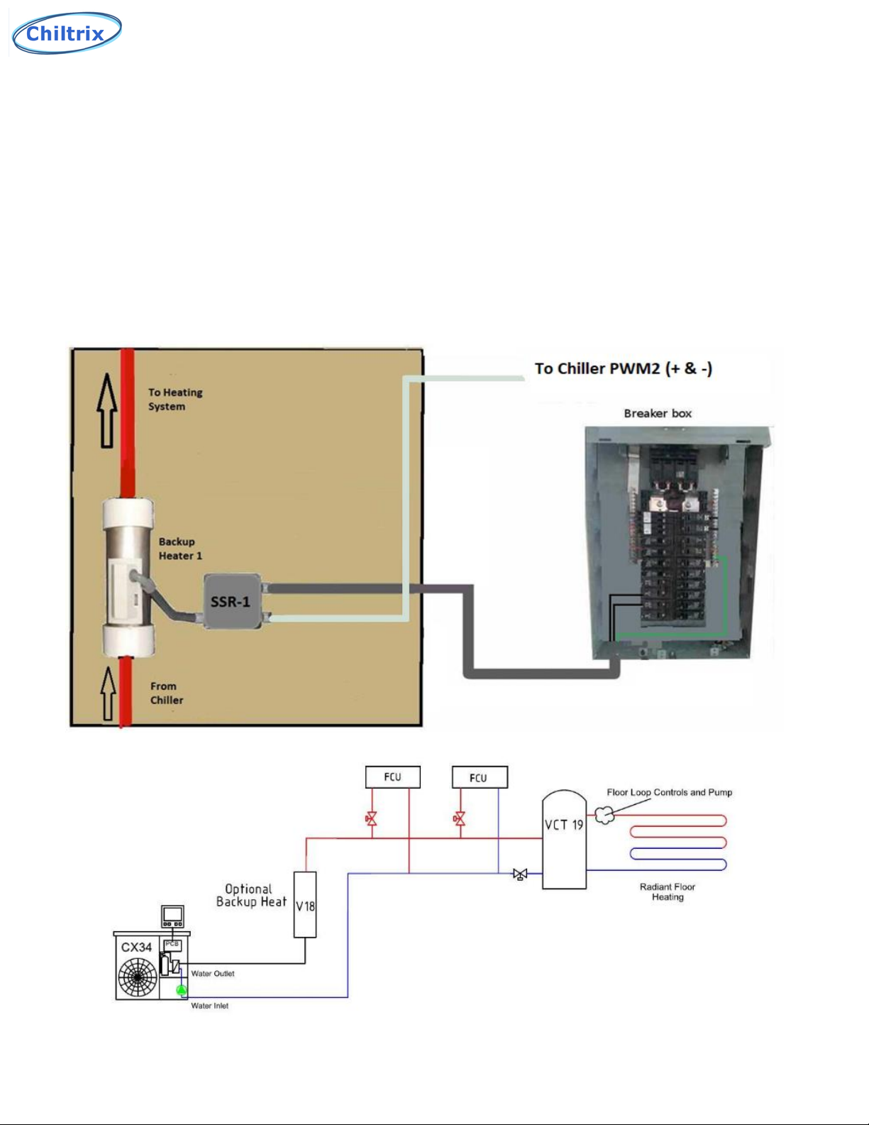
The power from one circuit breaker pole (L1) passes through the relay box and
connects directly to the in-line heater’s thermal overload interrupt device.
Power from the other circuit breaker pole(L2) is connected to the SSR and its
conductor is connected to the SSR’s terminal #2. The SSR’s terminal #1 is
connected to the in-line heater’s heating element. See below.
MAKE SURE GROUNDING IS DONE PROPERLY!
7

Assembly of this system and all connections to the buildings electrical
power system should be performed by a qualified licensed electrician
according to local and national electric codes. CHILLED WATER
IMPORTANT NOTE*
If the V18 will be installed in a
system that performs cooling
operation at times, make sure
to thoroughly seal around the
white ABS cover and inside
the Liquidtight conduit with
silicone as a minimum
precaution.
The requirement is to prevent
air from entering the V18
inside the white ABS cover
and contacting the cold pipe
or components which could
cause condensation to form
and accumulate inside the
unit.
For higher humidity locations
you may also consider filling
the entire cavity (but not
cover the reset button) with
an electronics-grade RTV
silicone potting material rated
for this type of application.
When using a potting
material, use it only per-code
and according to the
materials instructions, make
sure to allow the material to
fully cure before attaching the
cover.
Make sure power is
disconnected before and
during this operation. 8

Control Wiring
Output Cable
Control wiring from the PWM2 terminal to the SSR(s) consists of a cable
connected to the (+) red wire and the (-) black wire on the solid state
relay (SSR). If more than one in-line heater/SSR arrangement is used
then a jumper cable is used. It consists of a cable connecting the red to
(+) and black to (-) on both SSR’s putting them in a parallel configuration.
A junction box could also be used for this purpose (see illustrations on
page 6) .
9
CX34 Main Logic PCB shown above.

ASSEMBLING COMPONENTS
HEATER ELEMENT REPLACEMENT INSTRUCTIONS
CAUTION –During assembly/installation or after removing an element for
replacement, assure that all inner and outer sealing surfaces are clean and
free of debris prior to installing the new o-rings and element or leaks may
occur.
Step 1
Step 2
10
Visually inspect the element after installation and verify that that the
element is not in contact with the inside wall of the heater body. Failure
to do so may cause failure.
Inhaltsverzeichnis
Beliebte Heizung Handbücher anderer Marken


Empire Heating Systems
Empire Heating Systems WCC65 Bedienungsanleitung

Wetekom
Wetekom 92 86 43 Bedienungsanleitung

Desa
Desa SPC170-F Bedienungsanleitung

Watlow
Watlow Watrod Electric Tubular Heaters Bedienungsanleitung

Haverland
Haverland ECO-DRY GPS Series Stücklistenhandbuch

Stelpro
Stelpro ASILVC2060 Series Bedienungsanleitung