CLA-VAL 93-01 Betriebsanleitung

93-01/693-01
Distributed By: M&M Control Service, Inc.
www.mmcontrol.com/claval-index.php
800-876-0036 847-356-0566

This page was intentionally left blank!
Distributed By: M&M Control Service, Inc.
www.mmcontrol.com/claval-index.php
800-876-0036 847-356-0566

Distributed By: M&M Control Service, Inc.
www.mmcontrol.com/claval-index.php
800-876-0036 847-356-0566

Distributed By: M&M Control Service, Inc.
www.mmcontrol.com/claval-index.php
800-876-0036 847-356-0566

Distributed By: M&M Control Service, Inc.
www.mmcontrol.com/claval-index.php
800-876-0036 847-356-0566

This page was intentionally left blank!
Distributed By: M&M Control Service, Inc.
www.mmcontrol.com/claval-index.php
800-876-0036 847-356-0566

Distributed By: M&M Control Service, Inc.
www.mmcontrol.com/claval-index.php
800-876-0036 847-356-0566

This page was intentionally left blank!
Distributed By: M&M Control Service, Inc.
www.mmcontrol.com/claval-index.php
800-876-0036 847-356-0566

Description
The CIa-VaI Model 100-01 Hytrol Valve is a main valve for
CIa-VaI Automatic Control Valves. It is a hydraulically operated,
diaphragm-actuated, globe or angle pattern valve.
This valve consists of three major components; body, diaphragm
assembly, and cover. The diaphragm assembly is the only
moving part. The diaphragm assembly uses a diaphragm of nylon
fabric bonded with synthetic rubber. A synthetic rubber disc,
contained on three and one half sides by a disc retainer and disc
guide, forms a seal with the valve seat when pressure is applied
above the diaphragm. The diaphragm assembly forms a sealed
chamber in the upper portion of the valve, separating operating
pressure from line pressure.
Installation
1. Before valve is installed, pipe lines should be flushed of all
chips, scale and foreign matter.
2. It is recommended that either gate or block valves be
installed on both ends of the 100-01 Hytrol Valve to facilitate
isoIating the valve for preventive maintenance and repairs.
3. Place the valve in the line with flow through the valve in the
direction indicated on the inlet nameplate. (See “Flow Direction”
Section)
4. Allow sufficient room around valve to make adjustments and
for disassembly.
5. CIa-VaI 100-01 Hytrol Valves operate with maximum efficiency
when mounted in horizontal piping with the cover UP, however,
other positions are acceptable. Due to size and weight of the
cover and internal components of 8 inch and larger valves,
installation with the cover UP is advisable. This makes internal
parts readily accessible for periodic inspection.
6. Caution must be taken in the installation of this valve to insure
that galvanic and/or electrolytic action does not take place. The
proper use of dielectric fittings and gaskets are required in all
systems using dissimilar metals.
7. If a pilot control system is installed on the 100-01 Hytrol Valve,
use care to prevent damage. If it is necessary to remove fittings
or components, be sure they are kept clean and replaced
exactly as they were.
8. After the valve is installed and the system is first pressurized,
vent air from the cover chamber and pilot system tubing by
loosening fittings at all high points.
Tight Closing Operation
When pressure from the valve inlet (or
an equivalent independent operating
pressure) is applied to the diaphragm
chamber the valve closes drip-tight.
Full Open Operation
When pressure in diaphragm chamber
is relieved to a zone of lower pressure
(usually atmosphere) the line pressure
(5 psi Min.) at the valve inlet opens the
valve.
Modulating Action
Valve modulates when diaphragm pres-
sure is held at an intermediate point
between inlet and discharge pressure.
With the use of a Cla-Val. "modulating
control," which reacts to line pressure
changes, the pressure above the
diaphragm is varied, allowing the valve
to throttle and compensate for the
change.
Principles of Operation
Three Way
Pilot Control
Three Way
Pilot Control
Restriction
Modulating
Control
100-01
Hytrol Valve
MODEL
INSTALLATION / OPERATION / MAINTENANCE
Distributed By: M&M Control Service, Inc.
www.mmcontrol.com/claval-index.php
800-876-0036 847-356-0566

2
Flow Direction
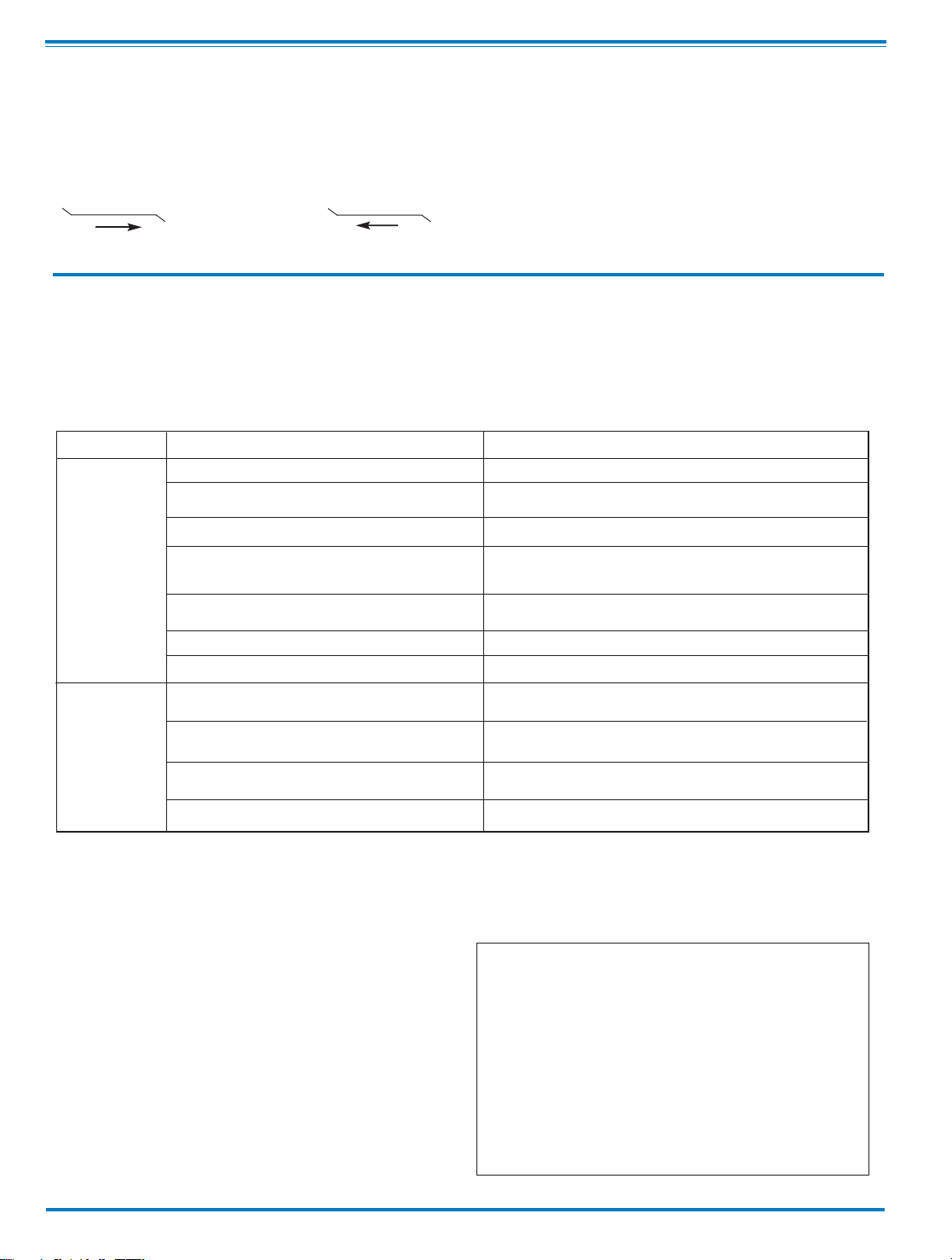
The flow through the 100-01 Hytrol Valve can be in one of two
directions. When flow is “up-and-over the seat,” it is in “normal”
flow and the valve will fail in the open position. When flow is “over-
the seat-and down,” it is in “reverse” flow and the valve will fail in
the closed position. There are no permanent flow arrow markings.
The valve must be installed according to nameplate data.
BRIDGEWALL INDlCATOR
Normal Flow Reverse Flow
Troubleshooting
The following troubleshooting information deals strictly with the
Model 100-01 Hytrol Valve. This assumes that all other compo-
nents of the pilot control system have been checked out and are
in proper working condition. (See appropriate sections in
Technical Manual for complete valve).
Three Checks
The 100-01 Hytrol Valve has only one moving part (the diaphragm
and disc assembly). So, there are only three major types of prob-
lems to be considered.
First: Valve is stuck - that is, the diaphragm assembly is not free
to move through a full stroke either from open to close or vice
versa.
Second: Valve is free to move and can’t close because of a worn
out diaphragm.
Third: Valve leaks even though it is free to move and the
diaphragm isn’t leaking.
Closed isolation valves in control system, or in main line.
Lack of cover chamber pressure.
Diaphragm damaged. (See Diaphragm Check.)
Diaphragm assembly inoperative.
Corrosion or excessive scale build up on valve stem.
(See Freedom of Movement Check)
Mechanical obstruction. Object lodged in valve.
(See Freedom of Movement Check)
Worn disc. (See Tight Sealing Check)
Badly scored seat. (See Tight Sealing Check)
Closed upstream and/or downstream isolation
valves in main line.
Insufficient line pressure.
Diaphragm assembly inoperative. Corrosion or excessive
buildup on valve stem. (See Freedom of Movement Check)
Diaphragm damaged. (For valves in "reverse flow" only)
After checking out probable causes and remedies, the following three checks can be used to diagnose the nature of the
problem before maintenance is started. They must be done in the order shown.
Open Isolation valves.
Check upstream pressure, pilot system, strainer, tubing, valves, or needle
valves for obstruction.
Replace diaphragm.
Clean and polish stem. Inspect and replace any damaged or badly eroded
part.
Remove obstruction.
Replace disc.
Replace seat.
Open isolation valves.
Check upstream pressure. (Minimum 5 psi flowing line pressure differential.)
Clean and polish stem. Inspect and replace any
damaged or badly eroded part.
Replace diaphragm.
Fails to Close
Fails to Open
CAUTION:
Care should be taken when doing the troubleshooting checks on
the 100-01 Hytrol Valve. These checks do require the valve to
open fully. This will either allow a high flow rate through the
valve, or the downstream pressure will quickly increase to the
inlet pressure. In some cases, this can be very harmful. Where
this is the case, and there are no block valves in the system to
protect the downstream piping, it should be realized that the
valve cannot be serviced under pressure. Steps should be
taken to remedy this situation before proceeding any further.
(cast into side of valve body)
SYMPTOM PROBABLE CAUSE REMEDY
Recommended Tools
1. Three pressure gauges with ranges suitable to the instal-
lation to be put at Hytrol inlet, outlet and cover connections.
2. Cla-Val Model X101 Valve Position Indicator. This pro-
vides visual indication of valve position without disassembly
of valve.
3. Other items are: suitable hand tools such as screw-
drivers, wrenches, etc. soft jawed (brass or aluminum) vise,
400 grit wet or dry sandpaper and water for cleaning.
All trouble shooting is possible without removing the valve from the
line or removing the cover. It is highly recommended to permanently
install a Model X101 Valve Position Indicator and three gauges in
unused Hytrol inlet, outlet and cover connections.
Distributed By: M&M Control Service, Inc.
www.mmcontrol.com/claval-index.php
800-876-0036 847-356-0566
Andere Handbücher für 93-01
1
Dieses Handbuch passt für folgende Modelle
1
Inhaltsverzeichnis
Andere CLA-VAL Regelventil Handbücher


