
COMITRONIC-BTI FURTIF Series Bedienungsanleitung
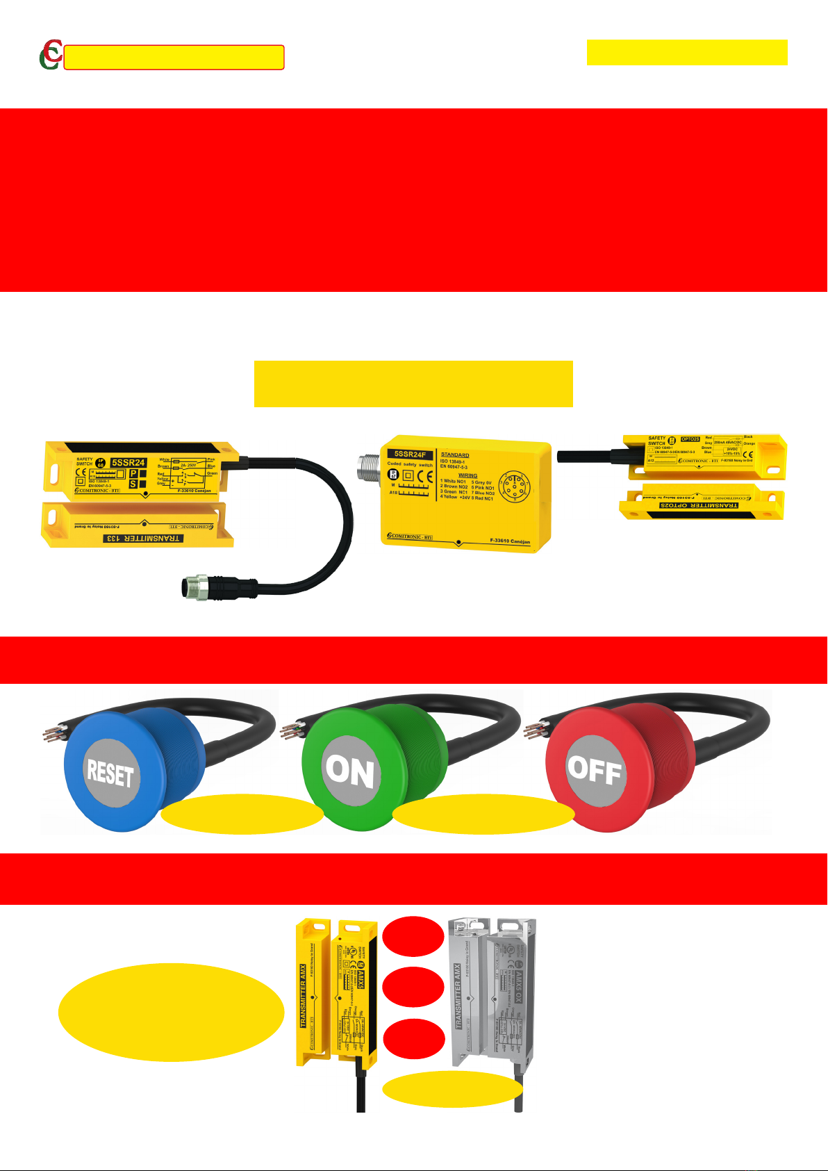
Stainless steel version Plastic/steel version
FURTIF RANGE
INSTRUCTION MANUAL "5SSR24-P/S/F, OPTO2S"
CONTACTLESS SAFETY SWITCH
FOR MACHINE SAFETY GUARDS / DOORS
new generationMade in France
SIL 2
CAT.3
Pld
2A pilot duty contact
2 million cycles at 2A
50 million mechanical cycles
3 years warranty
INNOVATION IS OUR DRIVING FORCE
ADAPTABILITY IS OUR CULTURE
COMITRONIC - BTI
OTHER PRODUCTIONS: FORCE 0 AND IP69K TOUCH BUTTON
COMITRONIC-BTI, LEADER OF THE STAND ALONE SAFETY SWITCH
STAND ALONE
SIL 1, PL c without external safety relay
Up to SIL 3, PLe with external safety relay

Contactless safety switch,
without polarity, stand alone,
with direct control of dangerous movement
CONTENTS
B10d: Beware of being trapped __________________________________________________________
1. Informations__________________________________________________________________
1.1. "Reed contact" technology_________________________________________________
1.2. ACOTOMtechnolgy_________________________________________________
1.3. MTTFd comparison_____________________________________________________
Locking devices for guards : ISO 14119___________________________________________________
2. Comparative technologies______________________________________________________
ACOTOM process
1. ACOTOM process____________________________________________________________
1.1. The birth of a revolutionary technology ___________________________________
1.2. Principle of ACOTOM process__________________________________________
Safety switches and RFID technology_____________________________________________________
1. RFID Technology______________________________________________________________
1.1. Why?________________________________________________________________
1.2 Disadvantages ________________________________________________________
1.3 Our RFID "AXKEF Process" Solution ______________________________________
5SSR24-P et 5SSR24-S_________________________________________________________________
2. Features_____________________________________________________________________
3. Installation Principle for 5SSR24-P_______________________________________________
4. Installation Principle for 5SSR24-S_______________________________________________
5. Assembly Instructions_________________________________________________________
6. Dimensions__________________________________________________________________
7. Recommendations____________________________________________________________
8. Periodic Inspection____________________________________________________________
5SSR24-F____________________________________________________________________________
2. Features_____________________________________________________________________
3. Installation Principle for 5SSR24-F for PL c________________________________________
4. Assembly Instructions_________________________________________________________
5. Dimensions__________________________________________________________________
7. Recommendations____________________________________________________________
8. Periodic Inspection____________________________________________________________
OPTO-2S_____________________________________________________________________________
2. Features_____________________________________________________________________
3. Installation Principle for PL c____________________________________________________
4. Assembly Instructions_________________________________________________________
5. Dimensions__________________________________________________________________
6. Recommendations____________________________________________________________
7. Periodic Inspection____________________________________________________________
DECLARATION OF CONFORMITY________________________________________________________
3
3
3
3
3
4
4
4
5
5
5
5
6
6
6
6
6
7
7
7
8
8
9
9
9
9
10
10
11
11
11
11
12
12
12
13
13
13
14
15
15
15
15
16

B10d: Beware of being trapped
3
1. Informations
For dry contact safety components, the Mean Time to Dangerous Failure (MTTFd)
depends on the nature of the load being switched. Software can be used as a tool to
determine the evaluation of machine application. Under no circumstances this software
allows the publication of the evaluation le. Instead, they should be considered more like
"ISO 13849-1 calculators."
Be aware of the B10d value, which must be listed with the corresponding load. In most
cases, the manufacturers give a B10d for a low current, such as 10 mA; this is the case
for reed switches, for example. In reality, this current is much higher. If the value of the
B10d is very high for 10 mA, it will be much lower at 100 mA and far too low at 1 A. In
this case, the MTTFd value will drop dramatically and the performance level of the ins-
tallation will be compromised. The results published by some software program should
therefore be taken lightly!
1.1 "Reed contact" technology
The usual notation is B10d at 20% of the rated current (In). If In = 50 mA, then B10d is
rated at 10 mA. This means that it is not possible to switch more than 10 mA with this
component. Some software will require the correction of this parameter.
Before choosing a component, check that the nature of the load to be switched corres-
ponds to 20% of In.
1.2 ACOTOM technology
The dry contacts of component X5 have a 8 A switching capacity limited to 1/4 of its value
to avoid any risk of sticking by carbonization. The value of the B10d is clearly displayed at
2 A with 2,000,000 cycles, which makes it possible to directly monitor power contactors.
1.3 MTTFd comparison with Dop=24 h/day, Hop=365 day/year, Tcy=1h
Technology MTTFd@10mA MTTFd with
1 contactor
MTTFd with
6 contactors //
Safe use of machines
REED 2283 impossible impossible with external controller+limiter at
10mA
ACOTOM2283 2283 2283 without controller external up to PLd
SYTCOM software: https://www.comitronic-bti.fr/fr/sytcom
A calculator for ISO 13849-1
• Easier to use
• More precise
• More complete
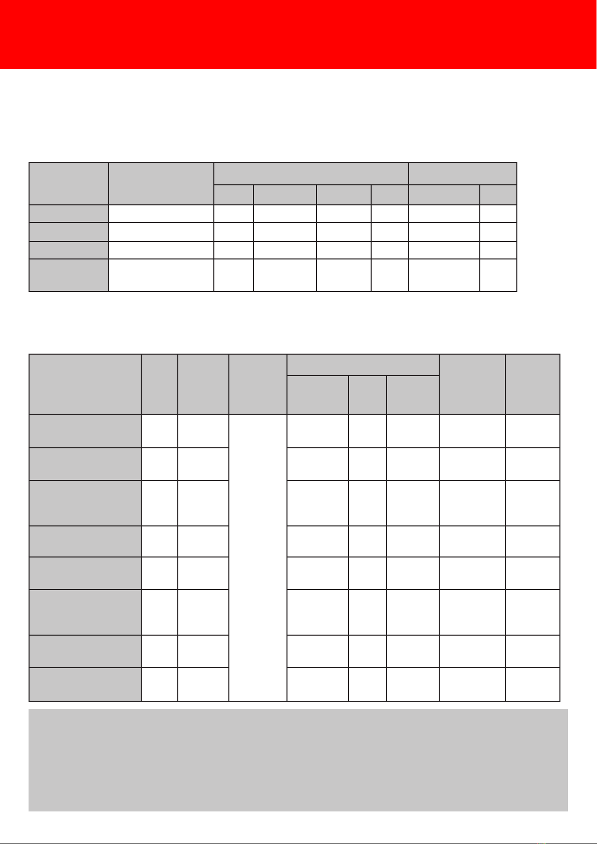
Locking devices for dangerous machinery guards are subject to ISO 14119. There are three dierent
technologies:
2. Comparative technologies
Locking devices
concerned by ISO 14119
4
Product Type Level
of
coding
Method
of
mounting
Possibility of assembly Direct
control of
movement
Food
industry
com-
pliance
Exposure Hid-
den
Flushed
roller switch 1 None Tamper-
proof
screws
or
Unre-
movable
screw
No Yes No Yes No
hinge switch 1 none Yes Yes No Yes No
key switch 2 low Subject
to condi-
tions
No No Yes No
reed switch 3 or
4
low Yes Yes No No low to
high
ACOTOMprocess 4 low to
medium
Yes Yes Yes Yes high
inductive safety
switch
3 low (by
dis-
tance)
Yes No No Subject to
conditions
No
transponder sensor 4 low to
medium
Yes No No Subject to
conditions
No
RFID safety switch 4 high Yes No No Subject to
conditions
No
Notes: The sensor equipped with the process ACOTOMis the only one that can be embedded in the
door and in the frame, even if the material is stainless steel or aluminum. This makes the sensor totally
invisible. Several forms of boxes are available, including an INOX M30 IP 69K version.
The sensor with the process ACOTOM3which is the only one that has a magnetic hold up to 4 Kg:
this is the BOSTER.
Since 2006, some of our sensors have a screw cover for invisible mounting and additional protection.
Technologies Device Power switch Sensor
Roller Hinge key Reed ACOTOMRFID
1 Mechanical X X X
2 Magnetic X X
3 Induction or RFID X
Standard
ISO 14119
Type 1 1 2 3
4
4 4
1. ACOTOMprocess : 5SSR24-S and 5SSR24-P safety switches
1.1. The birth of a revolutionary technology
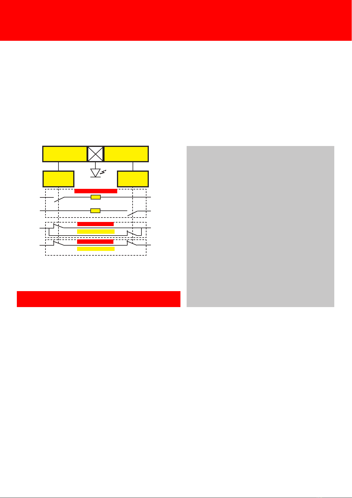
This system uses a double coded magnetic eld, one NC and two NO electromechanical safety contacts.
Despite a principle introduced on the market since 1993, this device is still the leader today thanks to
many advantages that remain unequalled to this day, such as 250V/2A safety contacts.
1.2. Principle of ACOTOM process
The system is composed of :
-Two anti-tamper and independently coded
magnetic eld detectors (redundancy)
- A low hysteresis control circuit
- A circuit that guarantees a very wide align-
ment tolerance
- Protection of the safety contacts at 1/4 of
their switching capacity to avoid any sticking
contacts
- A two-colour red/green LED indicating that
decoding is performed (green) or not perfor-
med (red)
- A diagnostic line indicates the status of the
sensor: version P=auxiliary information, ver-
sion S=no restart of the control circuit
- Direct monitoring of the dangerous move-
ment without using an intermediate safety
device, up to PL c, SIL 1, CAT 1.
5
DECODING
2
DECODING
1
RELAY RELAY
version 5SSR24P
safety contacts
version 5SSR24S
auxiliary contact
auxiliary contact
Replaces mechanical switches with its 2A/250V
switching capacity.
ACOTOMprocess

Miscellaneous information
Safety switches and RFID technology
1. RFID technology
1.1. Why?
The RFID in the safety switches represents an ideal solution only if you need a dierent code for each
guard, on each machine, and, in particular, for the sensors placed on the outside of the machines, or thus
accessible. Accableing to ISO 14119, RFID coding must be classied as "high". Pay attention because
some RFID safety switches have a "low" coding level, when they are provided with a unique code*; this
makes no dierence with our "ACOTOM process3". The standard does not impose a particular solution;
it depends on the needs of the application, or remains at the customer's discretion.
*Note: this unique coding requires code management and generates an additional workload for the
maintenance and purchasing departments.
1.2 Disadvantages
• RFID is a radio frequency technology and therefore the safety component cannot be concealed
behind a metal wall or embedded in the equipment. They are exposed to the environment, which
limits their scope. For example, they cannot be used in the food industry applications.
• Safety switches with RFID are often associated with OSSD safety contacts. This principle causes a
delay in the safety (OFF position) which is most important. The impact on the design of the machine
is real, and it is necessary to make an evaluation of the safety distance to check whether the position
of the access with respect to the dangerous movement should be modied.
• There are three types of components
- Those with a unique code: not interesting
- Those whose code is xed by construction
- In the event one of the parts breaks, it is necessary to replace both parts
- Those whose code is re-writable thanks to a special RFID key
- In the event one of the parts breaks, we can replace that part only
1.3 Our RFID "AXKEF Process" Solution
• XORF-SAI: a detection distance of 10 mm (nger protection)
• XORF-SA-MKT: a detection distance of 25 mm
• Delivery of a RFID key for erasing the code, as well as tamper-proof screws (from May 2018) and
washers
• Self learning programm (up to 16 million) through self-learning (AXKEF process): once installed, just
close the door and the code is transferred. Then, the recableing is locked.
• Dierent code each time or unique code upon request
• XORF-SA2: stand alone component SIL 2/PL d, with OSSD 500 mA safety contact
AXKEF
The solution for having a dierent code for each guard and on each machine
WITHOUT CODE MANAGEMENT
BY PURCHASING OR MAINTENANCE
6
7
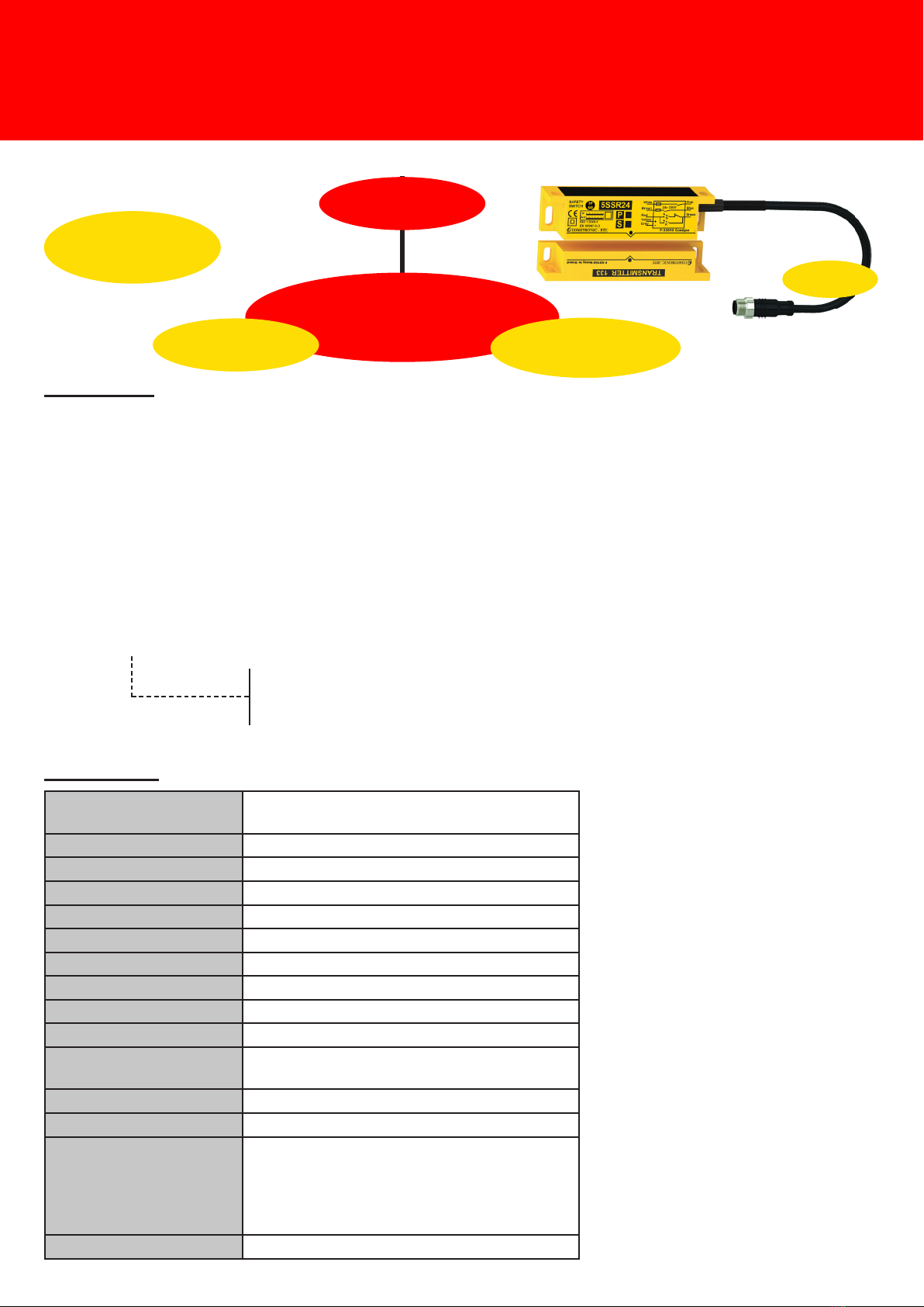
Contactless stand alone safety switch
with three potential-free contacts
5SSR24-P and 5SSR24-S
• Controls the opening of doors and movable guards on dangerous machines
• Robust product for the industrial environment
• Two NO contacts 250V / 2A and one NC contact, free of potential
• Two-colored diagnostic LED: red = inactive, green = active
• Embedded mounting possible (behind a 3mm wall, stainless steel, aluminum, no iron material)
• Connection to M12/8p connector compatible with T-SPLITTER (P version)
• Direct control of dangerous movement
Item code
5SSR24-o-o---------- MKT220: PUR 220cm M12/8p connector
P: parallel NC contact
S: NC contact series
F: RFID coding with self-learning
Power supply
IEC 60204-1 : PELV/SELV
24 VAC +/- 25% 50-60Hz
24 VDC +/- 25%
Operating current 50 mA (DC) / 115 mA (AC): maximum values
Protection Class Protection II, Pollution 3
Room temperature -30°C to +80°C (-22° to +176° F)
Protection Class IP 68
Vibration resistance 10~55 Hz, 1 mm double amplitude
Shock resistance 30 g, 11 ms
Frequency switching < 10 Hz
Response time <5ms (Ton)
Risk period
Contacts output AC1-AC15-DC13: 250 VAC / 2 A (2NO+1NC)
(5 VDC/10 mA minimum)
Indicator Two-color indicator red / green
Protection of contacts Internal fuse protection
Detection Distance
transmitter/receiver
(IEC 60947-5-3)
Sao=13 mm (Activation distance)
Sar=16 mm (deactivation distance)
Hysteresis 3 mm
M3D25AU2
Weight Transmitter: 66 g and Receiver: 150 g
2. Features
Connection
M12/8p
3 redundant contacts
250V/2A
LED diagnostics
Suitable for standard applications
of machine safety
IEC 62061: SIL 1
ISO 13849-1: PL c
2 colours led lighting
red=release (OFF)
green=works (ON)
The product is suitable
for hand protection
2A pilot duty contact
2 million cycles at 2A
50 million mechanical cycles
8
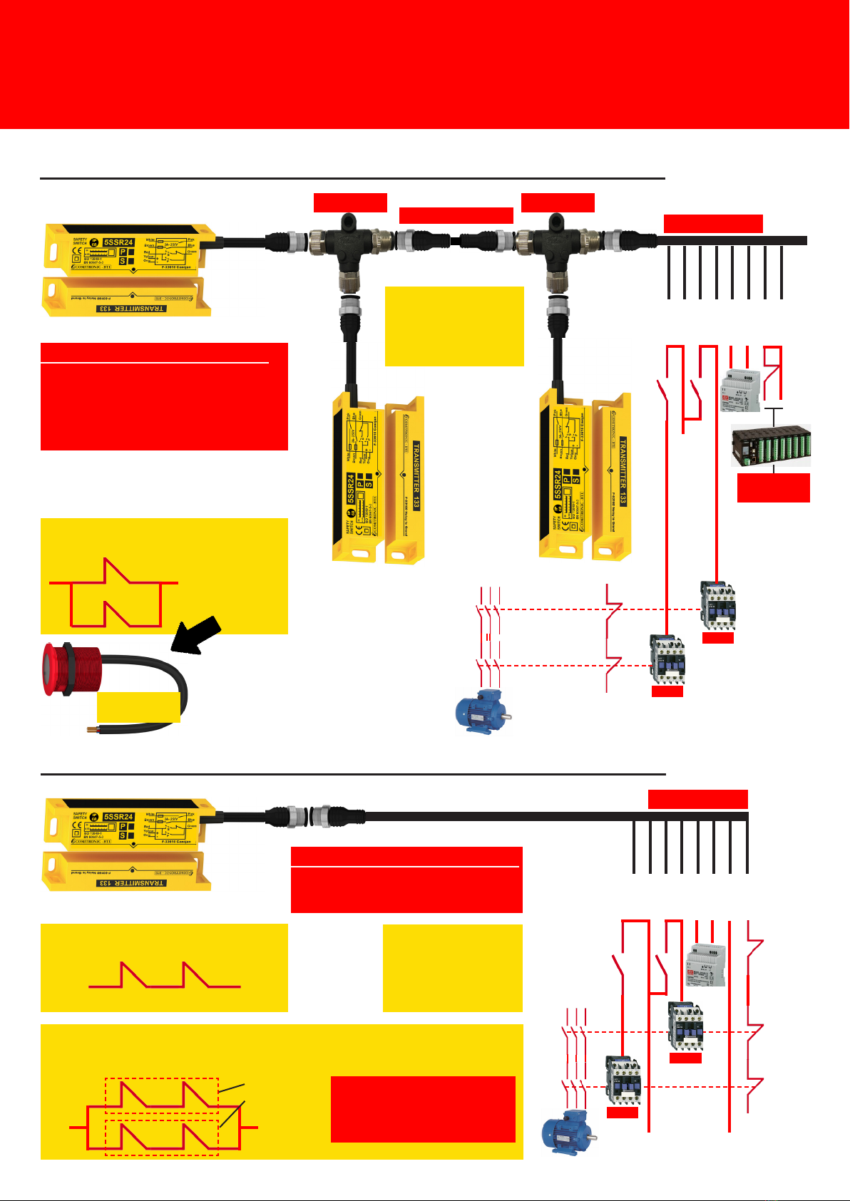
3. Principle of a 5SSR24-P installation for a PLc performance level
Equipment for this installation:
5SSR24-P: 3
T-Splitter: 2
FMKT: 2 m, 5 m or 10 m
FKT: 5 m, 10 m or 15 m
FKT cable
Brown
Blue
White
Pink
Yellow
Grey
Green
FMKT cable
Red
T-Splitter T-Splitter
2 7 1 6 4 5 3 8
info
door open
MKT Type A
KM1
KM2
3F24V
230V
4. Principle of a 5SSR24-S installation for a PLc performance level
FKT cable
Brown
Blue
White
Pink
Yellow
Grey
Green
Red
2 7 1 6 4 5 3 8
230V
KM1
KM2
3F
24V
testing
Equipment for this installation:
5SSR24-S
FKT: 5 m, 10 m or 15 m
testing
Detail of the auxiliary output :
redundancy is in parallel
for signalization
Indicator
V30 SPOT
Detail of the auxiliary output:
redundancy is series
to insert into a control circuit
Connection by the T-SPLITTER is possible, however the auxiliary lines
cannot be connected in series between the sensors. In this case they will be
connected in parallel.
3 8
sensor n°1
sensor n°2
The switching function of a
control circuit is not possible.
This combination is not use-
ful for machine safety.
Inductive loads such
as contactors must
be equipped with a
voltage limiter (diode,
lter, transil).
Inductive loads such
as contactors must
be equipped with a
voltage limiter (diode,
lter, transil).
Contactless stand alone safety switch
with three potential-free contacts
5SSR24-P and 5SSR24-S
9
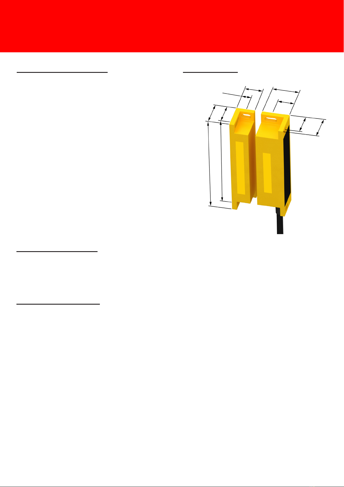
5. Assembly instruction 6. Dimensions
a) Drill the holes of the mounting bracket at F= 4.5 mm,
with a center distance of 83 mm
b) Use stainless steel BH4 tamper-proof screws supplied with the
product
c) It is important to use the stainless steel washers supplied
with the product.
(d) Once the door or casing is closed, the distance between
the transmitter and the receiver must be at least 1 mm.
This product should never be used as a mechanical stop.
e) Each element can be hidden behind a non-ferrous metal
wall 3 mm thick
f) The bending radius of the cable must be superior to
50 mm.
g) Connect the M12/8p connector
h) Test the installation
25
16
24.5
12.5
16.5
9.5
24.5
15
92
F 6
83
7. Recommendations
Protect the cable against external damage by using, for example, a mechanical shield (tube, mesh,
etc.). Keep a minimum gap of at least 1 mm between the transmitter and the receiver. These two parts
should not be used as mechanical stops.
8. Periodic inspection
This product should be checked periodically at least once a year. To do this, simply execute a procedure
and recable the results on a form. The following points must be checked:
Example of an assembly on a door:
• Move the transmitter 16 mm
• Observe that the LED lights up red
• Check that contacts 1-6 and 2-7 are open
• Check that contacts 3-8 are closed
• Approach the transmitter at 13 mm
• Observe that the LED lights up green
• Check that contacts 1-6 and 2-7 are closed
• Check that contacts 3-8 are open
• Close access
TRANSMITTER
RECEIVER
Contactless stand alone safety switch
with three potential-free contacts
5SSR24-P and 5SSR24-S
10
Contactless stand alone safety switch
with three potential-free contacts
5SSR24-F
• Controls the opening of doors and movable guards on dangerous machines
• Compatible with 25 x 25, 30 x 30, 35 x 35 grooved proles
• Robust product for the industrial environment, screw cover for a smooth surface
• Two NO contacts 250V / 2A and one NC contact, free of potential
• Two-colored diagnostic LED: red = inactive, green = active
• RFID coding with self-learning (discriminant or unique code on request)
• Connection to M12/8p connector compatible with T-SPLITTER
• Direct control of dangerous movement
Item code
5SSR24-o-o---------- MKT220: PUR 220cm M12 cable connection
P: parallel NC contact
S: Series NC contact
F: RFID coding with self-learning
Power supply
IEC 60204-1 : PELV/SELV
24 VAC +/- 25% 50-60Hz
24 VDC +/- 25%
Operating current 50 mA (DC) / 115 mA (AC): maximum values
Protection Class Protection II, Pollution 3
Room temperature -30°C to +80°C (-22° to +176° F)
Protection Class IP 68
Vibration resistance 10~55 Hz, 1 mm double amplitude
Shock resistance 30 g, 11 ms
Frequency switching 1 Hz max.
Response time 150 ms (Ton)
Risk period
Contacts output AC1-AC15-DC13: 250 VAC / 2 A (2NO+1NC)
(5 VDC/10 mA minimum)
Indicator Two-color indicator red / green
Protection of contacts Internal fuse protection
Detection Distance
transmitter/receiver
(IEC 60947-5-3)
Sao=10 mm (Activation distance)
Sar=11 mm (deactivation distance)
M3D25AU2
Weight Transmitter: 66 g and Receiver: 150 g
2. Features
Connection
M12/8p
3 redundant contacts
250V/2A
LED diagnostics
Suitable for standard applications
of machine safety
IEC 62061: SIL 1
ISO 13849-1: PL c
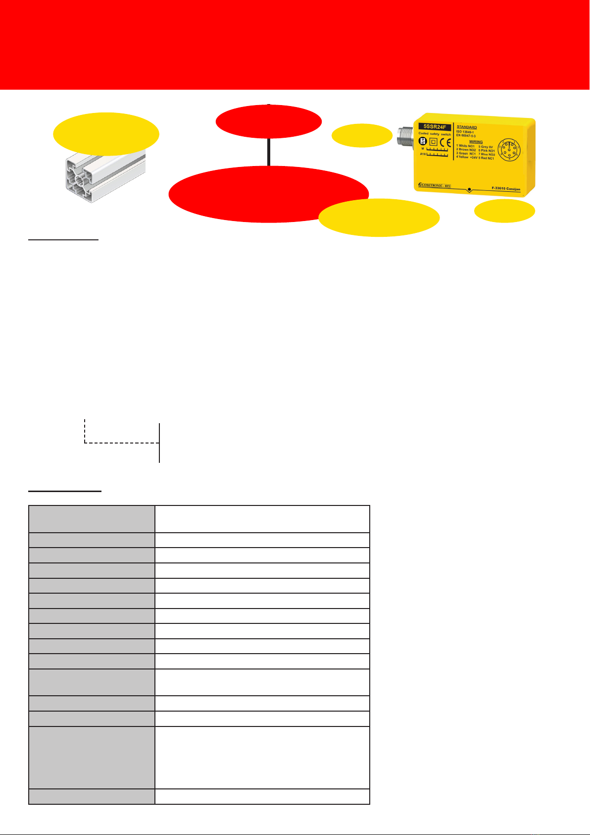
25 x 25 aluminum prole
aluminum prole 30 x 30
aluminum prole 35 x 35
New item
2019
The product is suitable
for nger protection
Dieses Handbuch passt für folgende Modelle
4
Inhaltsverzeichnis
Andere COMITRONIC-BTI Schalten Handbücher


