
Cooline PT036 Gebrauchsanweisung
INSTALLATION,
OPERATION
&
MAINTENANCE
MANUAL
SINGLE PACKAGED ROOF TOP AIR CONDITIONERS
'PT' SERIES
MODELS: PT036 - PT360
Part Number: 800-213-03

Contents Page
General
Model decoding ...................................................................................................................................................... 2
General statement .................................................................................................................................................. 3
Warranty ................................................................................................................................................................. 3
Safety issues .......................................................................................................................................................... 3
Inspection for damage ............................................................................................................................................ 3
Installation instructions
General................................................................................................................................................................... 4
Location of unit ....................................................................................................................................................... 4
Service clearance ................................................................................................................................................... 5
Rigging instructions ................................................................................................................................................ 5
Condensate drain connection................................................................................................................................. 6
Duct connection...................................................................................................................................................... 6
Electric heater ........................................................................................................................................................ 6
Unit weight & weight distribution ............................................................................................................................ 6
Unit dimensions ................................................................................................................................................. 7-11
Cable size............................................................................................................................................................. 12
Operation instructions
Start-up inspection & check list ............................................................................................................................ 12
Electrical data .................................................................................................................................................. 13-14
Performex controller, operation & functions .................................................................................................... 15-16
Crankcase heater ................................................................................................................................................. 16
Pump down control............................................................................................................................................... 16
Maintenance instructions
Airflow adjustment ................................................................................................................................................ 17
Crankcase heater ................................................................................................................................................. 17
Cleaning of coils & filters ...................................................................................................................................... 17
Belt tension testing procedure ......................................................................................................................... 17-18
Field wiring connections ....................................................................................................................................... 18
Preventive maintenance schedule ....................................................................................................................... 19
Trouble shooting chart ..................................................................................................................................... 20-21
Typical schematic wiring diagram.................................................................................................................... 22-29
Parts list ................................................................................................................................................................ 30
INDEX
CONTINUING RESEARCH RESULTS IN STEADY IMPROVEMENTS.
THEREFORE, THESE SPECIFICATIONS ARE SUBJECT TO CHANGE WITHOUT NOTICE.
1
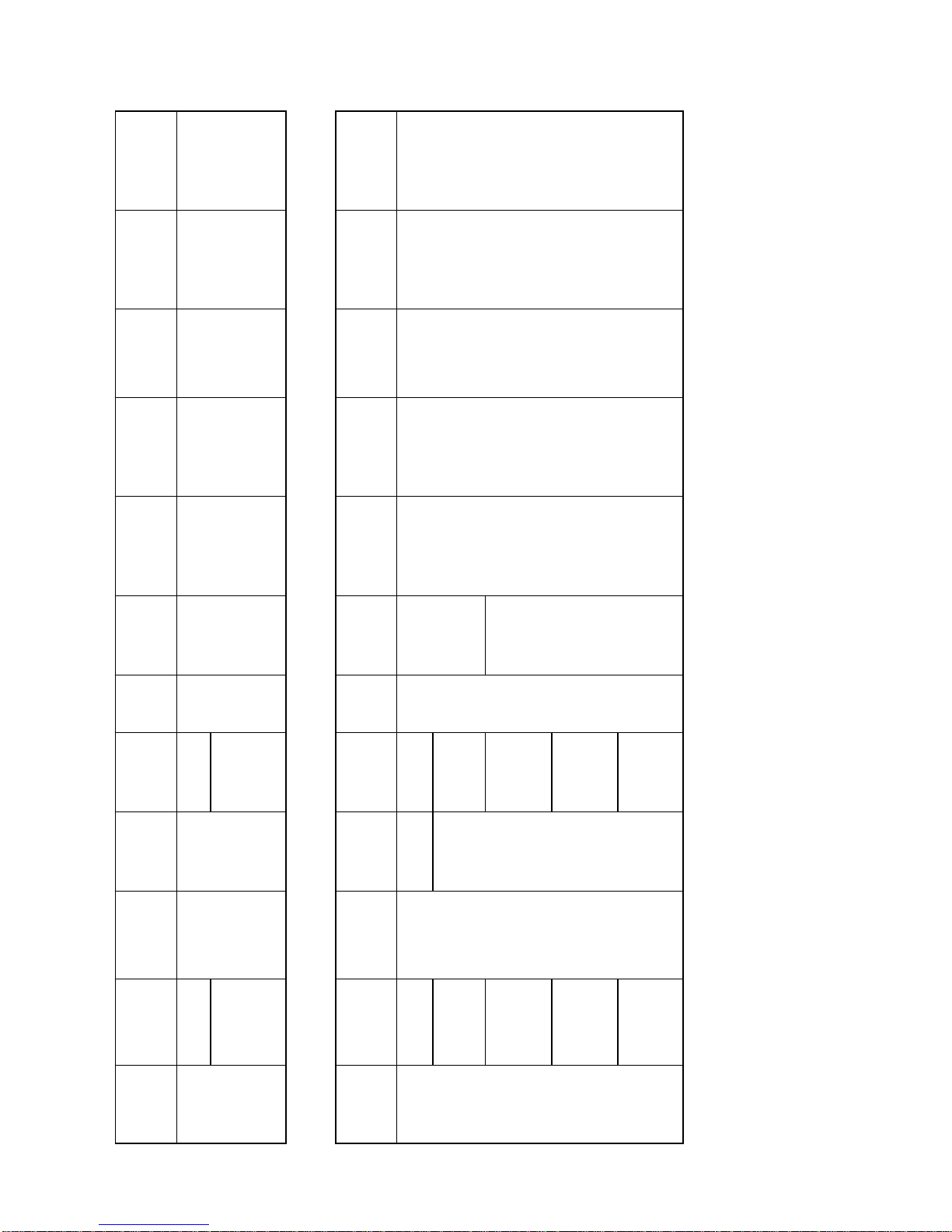
C : 1.5 HP ODP
D: 2 HP ODP
D: 2 HP ODP
E: 3 HP ODP
F: 3 HP TEFC
G: 5 HP ODP
H: 5 HP TEFC
J: 7.5 HP ODP
K: 7.5 HP TEFC
J: 7.5 HP ODP
K: 7.5 HP TEFC
L: 10 HP ODP
M: 10 HP TEFC
L: 10 HP ODP
M: 10 HP TEFC
N: 15 HP ODP
P: 15 HP TEFC
MODELS: PT075 - PT360 (BELT DRIVEN MOTOR)
1& 2
BASIC 3, 4 & 5
NOMINAL
COOLING
CAPACITY
(MBH)
8
BLOWER
MOTOR
6
ELECTRICAL
SUPPLY
( V-Ph-Hz )
10
HEATER
OPTIONS
(kW/STAGE)
12
CONDENSER
COIL
PT
COOLINE
PACKAGED
UNIT
036
048
060
W: 0.75 HP ODP
W: 0.75 HP ODP
Y: 1 HP ODP
L: 380/415-3-50
(4 WIRE) N: NO HEATER
A: 5/1
B: 6/1
C: 7.5/1
D: 10 /2
E: 12/2
J: IGT + ENHANCED
AL. FINS
K: IGT + ENHANCED
MHG. FINS
L : IGT + CORRU-
GATED CU. FINS
9
DRIVE
OPTIONS
N: DIRECT
DRIVE
11
EVAPORATOR
COIL
J: IGT + ENHANCED
AL. FINS
K :IGT + ENHANCED
MHG. FINS
L : IGT + CORRU-
GATED CU. FINS
15
UNIT
ACCESSORIES
N: STANDARD UNIT
C:FRESH AIR
MANUAL
DAMPER
MODELS: PT036 - PT060 (DIRECT DRIVE MOTOR) MODEL DECODING
7
REFRIGERA-
TION CIRCUIT
S: SINGLE
14
OTHER
OPTIONS
N: STANDARD UNIT
I: ANTI-ICE
U:UVM
V: VOLT FREE
CONTACT
13
PDS
OPTION
N: NO PDS
OPTION
P: PDS OPTION
1& 2
BASIC 3, 4 & 5
NOMINAL
COOLING
CAPACITY
(MBH)
8
BLOWER
MOTOR
6
ELECTRICAL
SUPPLY
( V-Ph-Hz )
10
HEATER
OPTIONS
(kW/STAGE)
12
CONDENSER
COIL
PT
COOLINE
PACKAGED
UNIT
075
090
100
120***
180
215
240
300
360
L: 380/415-3-50
(4 WIRE)
N: NO HEATER
A: 5/1*
B: 6/1*
C: 7.5/1
D: 10 /2
E: 12/2
F: 15 /2
G: 20 /2
C: 7.5/1
D: 10 /2
E: 12/2
F: 15 /2
G: 20 /2
H: 25/2
J: 30/2**
J: IGT + ENHANCED
AL. FINS
K: IGT + ENHANCED
MHG. FINS
L : IGT + CORRU-
GATED CU. FINS
9
DRIVE
OPTIONS
J: ALT. I
K: ALT. II
11
EVAPORATOR
COIL
J: IGT + ENHANCED
AL. FINS
K :IGT + ENHANCED
MHG. FINS
L : IGT + CORRU-
GATED CU. FINS
15
UNIT
ACCESSORIES
N: STANDARD UNIT
C:FRESH AIR
MANUAL
DAMPER
7
REFRIGERA-
TION CIRCUIT
S: SINGLE
14
OTHER
OPTIONS
N: STANDARD UNIT
I: ANTI-ICE
U:UVM
V: VOLT FREE
CONTACT
13
PDS
OPTION
N: NO PDS
OPTION
P: PDS OPTION
NOTE:*– Applicable for PT075 models only.
** – Applicable for models PT180 & above only.
*** – 3 HP motor only available for PT120.
D:DUAL
2
GENERAL
GENERAL STATEMENT
This unit is from the PT series that was designed & built for the optimum performance. However, it is required that you become well
acquainted with good practices for the proper installation/operation/and maintenance procedures in order to ensure a safe trouble free
operation, year after year.
Please read through the whole manual contents before you attempt to install/operate/ and maintain the unit.
Most of the procedures described in this manual require certain skills and experience. The installation and other maintenance procedures
should be performed only by highly skilled and experienced technicians. The end user’s role should be limited to the cleaning of the
filter.
Please consult your nearest “COOLINE” representative for further information.
The PT units can be supplied, depending on the End User requirement, as the basic “Cool Only” version, or the “Heat & Cool” version
(with electric heater module).
WARRANTY
All of the PT series of Packaged Roof Top Units are covered by the standard warranty terms against any manufacturer defect. Should
you encounter any problem that falls under the warranty terms please contact your nearest “COOLINE” representative.
SAFETY ISSUES
There are three degrees of safety hazards that are identified throughout this manual as WARNING (where the situation will result in
personal injury), CAUTION (where personal injury might occur), and ATTENTION (where minor personal injury and/or property dam-
age could happen). Please understand and respect those identifications.
WARNING: The PT units operate on a high voltage with moving parts (at high speed) which can lead to serious injuries and/
or damage to the unit. Never attempt to service the unit unless the main electrical power supply has been disconnected.
CAUTION: Extra care should be observed when installing, test running, adjusting, servicing, or maintaining the unit as the
hazard of explosion, fire, electrical shock, and potential personal injury and property damage are present.
When performing any task pertaining to the installation and maintenance of the unit, the skilled technician should observe all the
applicable safety measures (wear of safety helmet, boots, gloves, and goggles. Use of proper handling materials for brazing and use
of wet cloth for quenching. A fire extinguisher should be easily accessible etc.). He should also read all the instructions and information
in this Manual prior to attempting to perform any installation or servicing of the unit.
All applicable local codes should also be observed.
INSPECTION FOR DAMAGE
The unit should be carefully inspected visually for any sign of physical damage due to mishandling. Whenever a damage is detected,
please indicate it on the corresponding delivery note before you sign it and inform your nearest “COOLINE” office.
3
GENERAL
These units are shipped completely assembled, charged, and wired. They do not require any field installation of refrigerant tubing.
Units require external power, thermostat wiring, condensate drain piping and ducting as applicable.
Size of unit for an installation should be based on a heat gain calculation made according to applicable standards. Units must also be
installed in accordance with regulations of the "National Fire Protection Association" and local electrical codes. Where local regulations
conflicts with the instructions in this manual, installer should adhere to local standards.
Prepare your concrete pad or steel stand based on the corresponding dimensions. Remove shipping protective covers and wooden
crating and lift unit from base and place in position with suitable rubber vibration isolators.
All field installed accessories are to be installed by the customer with necessary reinforcements as required.
LOCATION OF UNIT
When selecting the location for the unit, the following points should be kept in mind:
1. Provisions for a concrete pad or steel stand base.
2. That the terrain allows for drainage away from the unit.
3. If the unit is to be roof mounted, inspect the roof for load bearing capacity. The roof should have sufficient structural strength to
carry the weight of the unit.
4. Install unit on vibration isolation pads, i.e. on rubber mounting pads.
5. Availability of electric power.
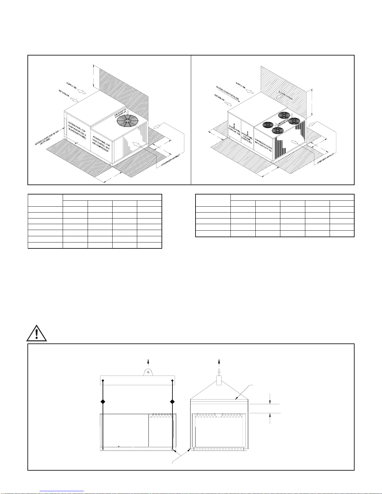
6. To position the unit for unrestricted air circulation of the condenser air inlet and to prevent any possibility of air recirculation from the
condenser fan discharge air (see figure on next page).
7. Check minimum clearances required for your unit, with regard to walls, or other obstructions (see figure on next page).
8. Air cooled equipment should not be installed under low structural overhangs which can cause condenser air recirculation or
restriction. Observe minimum of clearance (see figure on next page).
9. Care should be taken to prevent air from other sources from entering condenser, if this air is at a high temperature.
10. Level the unit on its final location and be sure that the levelling tolerance is ±5 mm per linear meter in any direction.
CAUTION: Do not install the unit as indoor unit, install it in an open area, and unit air inlets must not be located near exhaust
vents or other source of contaminated air.
INSTALLATION INSTRUCTIONS
4
B
C
A
E
D
B
C
D
A
ATTENTION TO RIGGERS
•Insert 2" nominal pipe through holes in the base rail as shown in the figure below for slings.
•Holes in base rail are centered around the unit center of gravity.
•Use wooden pallet or spreader bar when rigging, to prevent the slings from damaging the unit.
•Rollers may be used to move the unit on the roof or ground.
CAUTION: All panels should be in place when rigging.
RIGGING INSTRUCTIONS
MODELS: PT036 - PT360
5
SERVICE CLEARANCE
MODEL DIMENSIONS
NUMBER A B C D
PT036 85 105 85 150
PT048 85 105 85 150
PT060 85 105 85 150
PT075 90 105 90 200
PT090 90 105 90 200
PT100 90 105 90 200
PT120 90 105 90 200
NOTE: All dimensions are in cm.
A :Clearance dimension from condenser coil
B : Clearance dimension from compressor, control box, blower, evaporator coil & filter
C : Clearance dimension from condenser coil & filter
D : Clearance dimension over the condenser fan
MODEL DIMENSIONS
NUMBER A B C D E
PT180 120 120 115 250 90
PT215 120 120 115 250 90
PT240 120 120 115 250 90
PT300 120 120 115 250 90
PT360 120 120 115 250 90
A : Clearance dimension from condenser coil
B : Clearance dimension from compressor, control box & evaporator coil
C : Clearance dimension from condenser coil & blower
D : Clearance dimension over the condenser fan
E : Clearance dimension from filter access panel
MODELS: PT036 - PT120 MODELS: PT180 - PT360
NOTE: Only two condenser fans for models PT180 - PT240.
SPREADER BAR
NOMINAL PIPE THRU UNIT FOR SLINGS TO AVOID BASE DAMAGE.
END
PROPER CLEARANCE TO BE
PROVIDED.
COMPRESSOR
LIFT LIFT
2. PIPE DIA 2" FOR PT090 TO PT360 MODELS
1 .PIPE DIA 1 1/2" FOR PT036 TO PT075 MODELS
Note:
CONDENSATE DRAIN CONNECTION
•Use standard PVC pipe with NPT connection for the condensate drain. Provide a 'P' trap immediately at the condensate drain connection.
•Piping has to be sloped away from the unit.
•Remember to remove the drain hole plug before operating the unit. Avoid bends & elbows.
DUCT CONNECTION
The units can be connected to the ducting in horizontal configuration. Connect ducting using flexible duct connection. The duct should
be properly designed and the drive package should match the required CFM & corresponding external static pressure.
ATTENTION: Avoid abrupt changes in size and/or direction of duct to ensure proper unit performance.
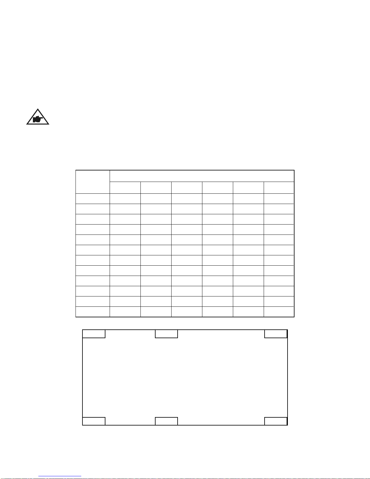
UNIT WEIGHT & WEIGHT DISTRIBUTION
ELECTRIC HEATERS
Electric heater kit is installed in the unit at the supply air opening space.
MODEL
NUMBER
WEIGHTS (Kg.)
JKML
PT036
PT048
PT060
PT075
PT090
PT100
PT120
PT180
PT215
PT240
PT300
PT360
36
41
45
52
92
91
91
99
89
94
130
145
51
57
62
70
95
98
98
152
94
98
202
216
34
39
42
45
73
73
73
85
101
105
148
151
-
-
-
-
-
-
-
108
177
181
221
249
PQ
-
-
-
-
-
-
-
105
103
107
158
175
JP K
MQ L
CONDENSER SECTION
SUPPLY AIR/
RETURN AIR
67
72
76
86
116
134
135
155
182
186
226
256
6
=
=
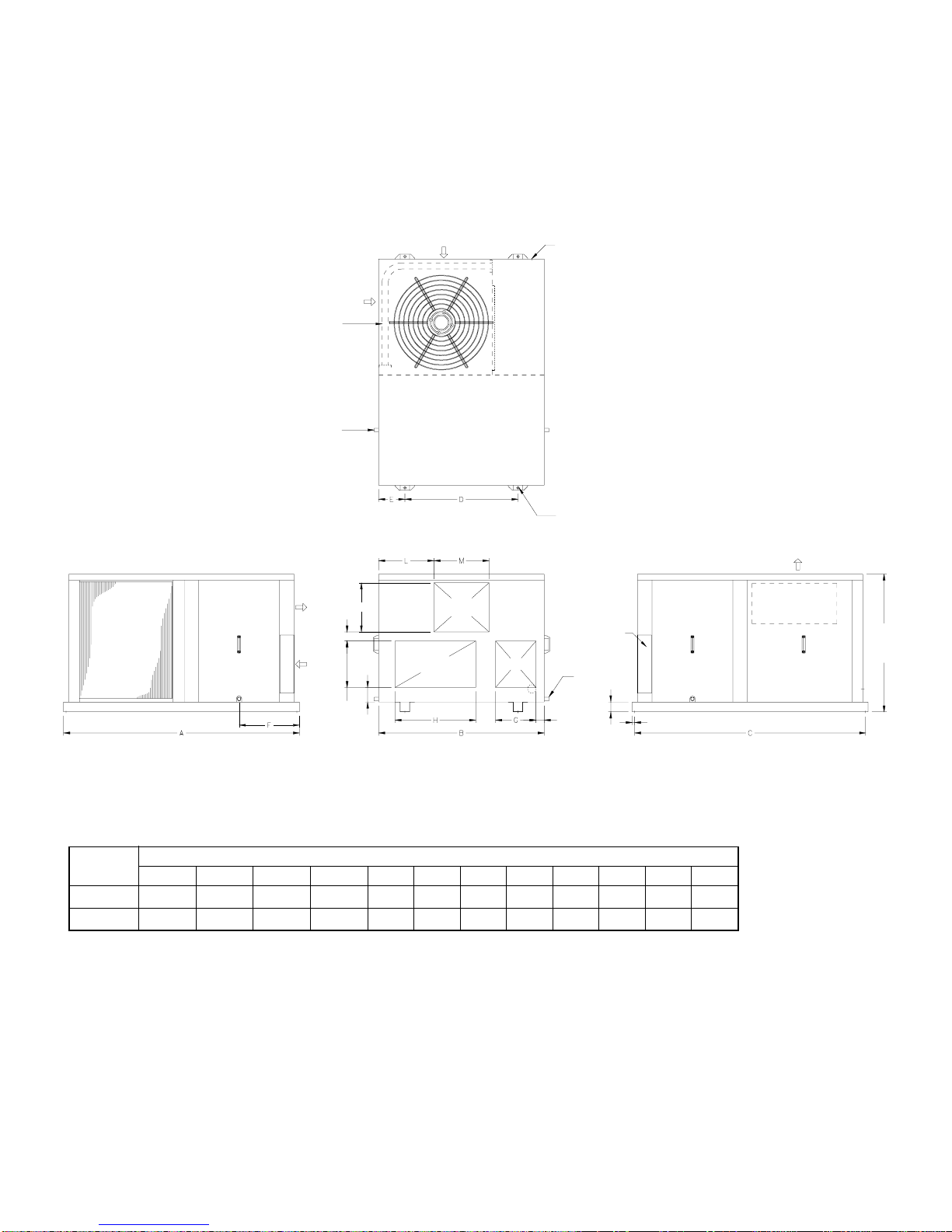
UNIT DIMENSIONS
PT036 - PT075
ABCDEFGHJKLM
PT036 - PT060 1460(57.48) 1025(40.35) 1430(56.3) 700(27.56) 163(6.42) 373(14.68) 250(9.84) 500(19.69) 57(2.24) 304(11.96) 343(13.49) 340(13.39)
PT075 1775(69.88) 1150(45.28) 1745(68.7) 800(31.5) 175(6.89) 480(18.9) 325(12.8) 672(26.46) 80(3.15) 280(11.02) 275(10.83) 600(23.62)
MODEL DIMENSIONS
NOTE:
1. All dimensions are in mm (dimensions in brackets are in inches).
2. Service clearance should be 1200mm (4 feet) on all sides.
7
CONDENSATE DRAIN OUTLET [BOTH ENDS]
MOUNTING HOLES Ø
13 [0.5] [ 4 EACH]
K
J
286 [11.27]
90 [3.53]
51 [2.00] 15 [0.59]
61 [2.41]
850 [33.46]
FRESH AIR
OPENING
POWER SUPPLY INLET
DRAIN OUTLET
[BOTH ENDS]
FILTER ACCESS
PANEL [BOTH ENDS]
CONDENSER COIL
CONDENSER COIL
COMPRESSOR/CONTROLS
ACCESS PANEL
ACCESS PANEL
FOR BLOWER
AND MOTOR
AIR IN
RETURN AIR
SUPPLY AIR
AIR OUT
AIR IN
SIDE VIEW
COMPRESSOR/CONTROL
COMPARTMENT
SIDE VIEW
FRONT VIEW
TOP VIEW
RETURN AIR
OPENING
SUPPLY
AIR
OPENING
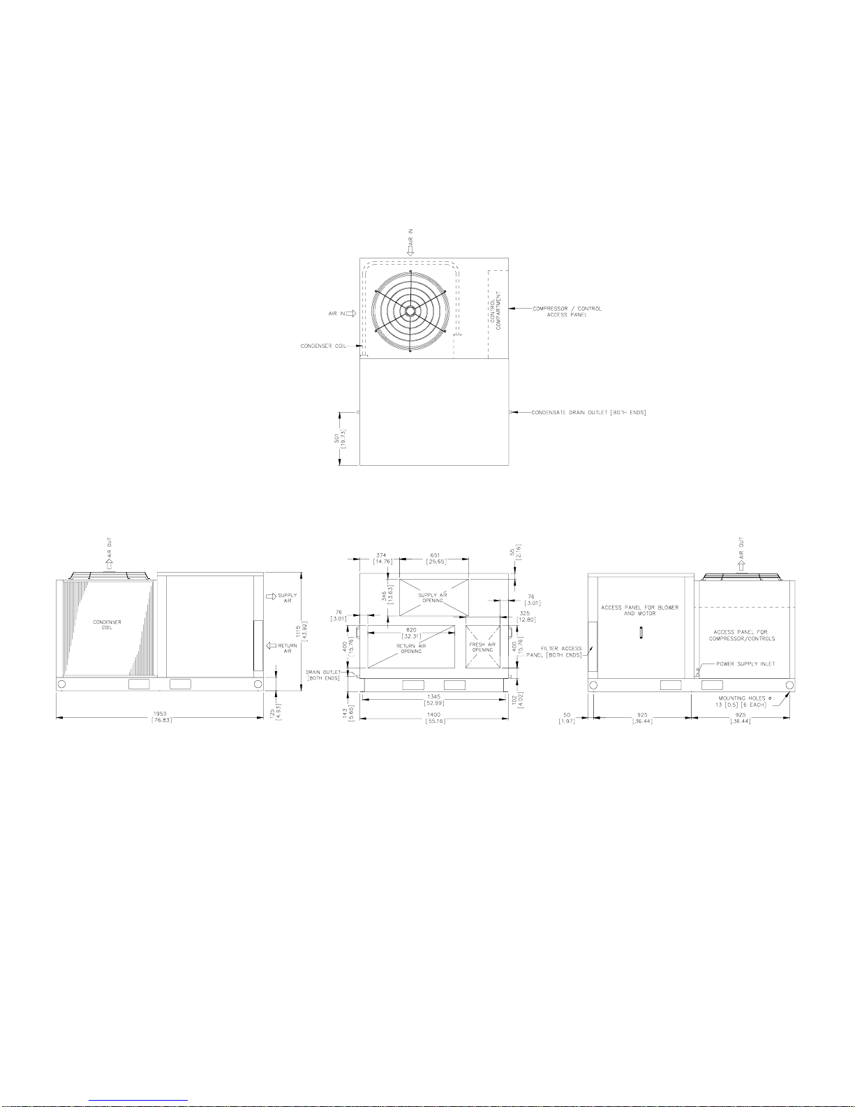
UNIT DIMENSIONS
PT090 - PT120
NOTE:
1. All dimensions are in mm (dimensions in brackets are in inches).
2. Service clearance should be 1200mm (4 feet) on all sides.
8
SIDE VIEW SIDE VIEWFRONT VIEW
TOP VIEW
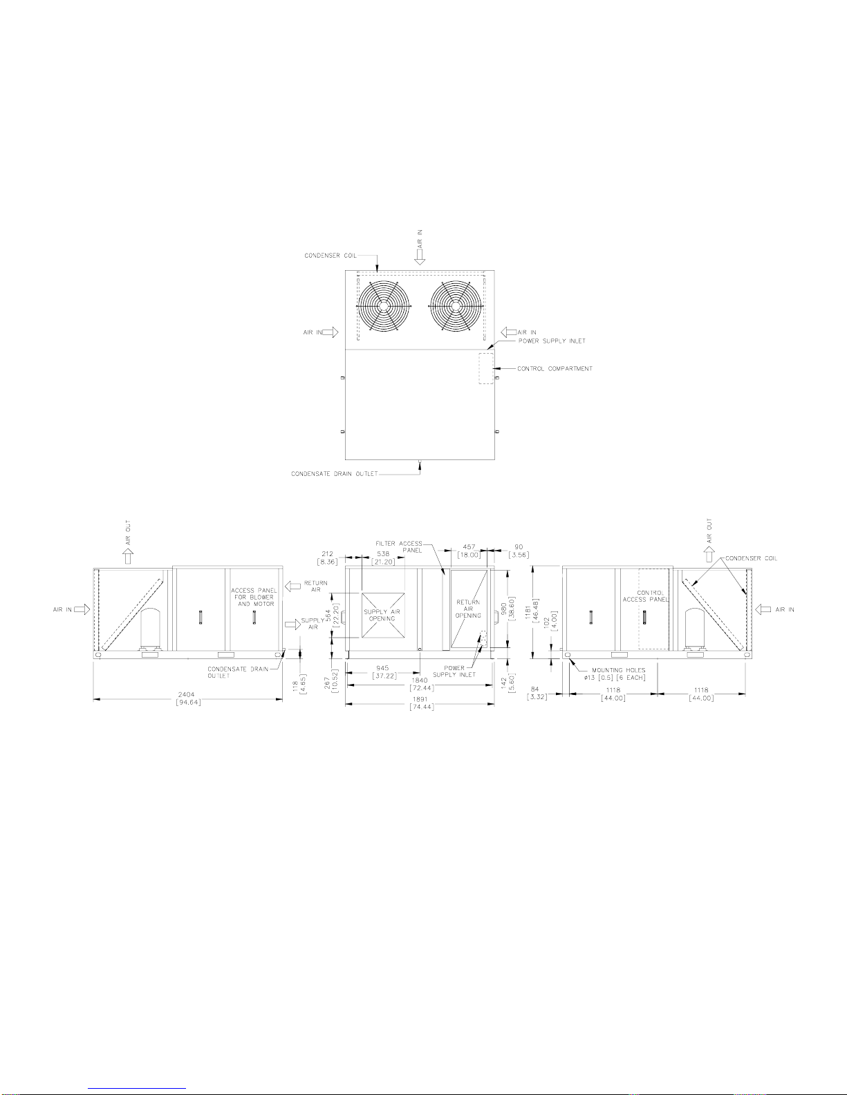
UNIT DIMENSIONS
PT180
NOTE:
1. All dimensions are in mm (dimensions in brackets are in inches).
2. Service clearance should be 1200mm (4 feet) on all sides.
9
SIDE VIEW SIDE VIEWFRONT VIEW
TOP VIEW
Dieses Handbuch passt für folgende Modelle
11
Inhaltsverzeichnis
Andere Cooline Klimaanlage Handbücher


