Creatix LC 144 VF Bedienungsanleitung

LC 144 VF
HIGH SPEED MODEM for
• • Data Transmission
• • Fax
• • Speech Messages
User Manual
CREATIX Polymedia GmbH
Fasanerieweg 15
66121 Saarbrücken
Dieses Dokument wurde erstellt mit FrameMaker 4.0.4.

CREATIX Polymedia GmbH, Saarbrücken 1994
This handbook is protected by copyright. It must not be copied, reproduced,
translated or transmitted in electronic media, in whole or in part.
Accuracy of the information is not guaranteed.
Any mention in this handbook of products made by other manufacturers is
for information purposes only and represents no misuse of trademarks.
jüt mv205a0.133e

I
Table of contents
Chapter 1 INTRODUCTION 1-1
What is a Modem ? 1-1
About this Modem 1-1
Special Features 1-2
General Description 1-2
Installation Instructions 1-2
Basic Adjustments 1-3
Chapter 2 AT COMMANDS:
DATA MODEM 2-1
Guidelines for Using AT Commands 2-1
AT - Attention Code 2-4
The ESC Sequence 2-4
A - Answer Mode 2-4
A/ - Repeat Last Command Line 2-5
B - BELL/CCITT Standard 2-5
D - Automatic Dialling and Dialling Parameters 2-5
E – Echo Function 2-6
F – Determining Type of Modulation and Speed 2-6
H – Switch Hook Check (Replace Handset) 2-7
I – Firmware Information 2-7
L – Volume Level of Connected Loudspeaker 2-7
M – Switching the Loudspeaker On and Off 2-7
N – Recognizing Type of Modulation 2-7
O – Return to On-Line Operation 2-8
P – Selecting Pulse Dialling 2-8
Q – Modem Messages On / Off 2-8
S – Reading and Modifying Registers: 2-8
T – Selecting Tone Dialling 2-8
V – Verbal or Numeric Modem Messages 2-8
W – Controlling Connect Messages 2-8
X – Extended Connect Messages; Making Connections 2-9
Y – Long Space Disconnect 2-9
Dieses Dokument wurde erstellt mit FrameMaker 4.0.4.

II
Z – Reset/Load a Stored Profile 2-10
&C – M5 Control Line 2-10
&F – Loading the Factory Settings 2-10
&G – Guard Tone 2-11
&K – Flow Check 2-11
&M – Asynchronous Dialling / Synchronous Data Transmission 2-11
&Q – Synchronous / Asynchronous 2-11
&R – Control Lines S2 and M2 2-12
&S – Control Line M1 (107/DSR) 2-12
&T – Modem Test Functions 2-12
&V – Displaying the Current Configuration 2-13
&W – Storing a set Profile 2-13
&X – Setting the Clock Signal in Synchronous Mode 2-14
&Y – Selecting a Start Configuration 2-14
&Z – Telephone Number Storage 2-14
\A – Maximum MNP Block Size 2-14
\B – Sending a Break Signal 2-14
\F – Displaying the Telephone Number Store 2-15
\G – Modem/Modem Flow Check 2-15
\J – Baud rate Adjustment via the Computer 2-15
\K – Type of Break Control 2-16
\L – Determining Block/Stream Mode with MNP 2-16
\N – Data Transmission Mode 2-16
\S – Displaying the Configuration 2-17
\W – Split Speed Operation 2-17
-K – Extended MNP Operation 2-17
%C – Authorise Data Compression 2-18
%E – Automatic Retrain 2-18
%F – 75Tx/1200Rx or 1200Tx/75Rx in V.23 Mode 2-18
*H – Handshake Speed with MNP 10 Modem: 2-18
*C – Password for Remote Configuration 2-18
*R – Remote Configuration 2-19
*E – End Remote Configuration 2-19
*P – Password for Automatic Callback 2-19
*L – Displaying Callback Numbers 2-20

III
Chapter 3 DIALLING WITH V.25.Bis 3-1
Chapter 4 MODEM MESSAGES 4-1
Chapter 5 S-REGISTERS 5-1
S0 – Number of Ring Characters before Modem engages 5-2
S1 – Ring Character Counter 5-2
S2 – Esc Sequence Character 5-2
S3 – Carriage Return Character 5-2
S4 – Line Feed Character 5-2
S5 – Backspace Character 5-3
S6 – Waiting Time for Dialling Tone 5-3
S7 – Waiting for Carrier Signal 5-3
S8 – Pause Time after Comma 5-3
S9 – Answer Time after Carrier Recognition 5-3
S10 – Delay between Carrier Loss and Hanging Up 5-4
S12 – Guard Time for Esc Sequence 5-4
S14 – General Options 5-4
S16 – Modem Test Options 5-5
S18 – Test Timer 5-5
S19 – Autosync Register 5-6
S20 – HDLC Address/BSC Synchronous Character 5-6
S21 – V.24/General Options 5-6
S22 – Loudspeaker/Authorised Modem Messages 5-7
S23 – General Options 5-7
S24 – Current Saving Switch 5-8
S25 – DTR Delay Time 5-8
S26 – Delay RTS to CTS 5-8
S27 – General Options 5-8
S28 – General Options 5-9
S29 – Flash Dial Modifier Time 5-9
S30 – Inactivity Timer 5-9
S31 – General Options 5-10
S32 – XON Character 5-10
S33 – XOFF Character 5-10
S36 – Fallback on V.42 Connection Set-up 5-10

IV
S37 – Speed on the Telephone Line 5-11
S38 – Delay before Hanging Up 5-11
S39 – Flow Control 5-11
S40 – General Options 5-12
S41 – General Options 5-12
S46 – Authorising a Data Compression 5-13
S48 – Directing the V.42 Handshake 5-13
S80 – Soft Switches 5-13
S82 – Treating the Break Signal 5-13
S86 – Error Codes for NO CARRIER Messages 5-14
S95 – Extended Connection Messages 5-14
TECHNICAL INFORMATION A-1
Digital Interfaces A-1
Audio Jack A-1
LED Indicators A-2
GLOSSARY A-2
CCITT RECOMMENDATIONS A-3
Technical Specifications A-4

INTRODUCTION 1-1
Chapter 1 INTRODUCTION
The Data Modem you have purchased represents the latest state of the art in data
communication; its comprehensive facilities provide all you will need for profes-
sional data transfer purposes.
In data modem mode, you can achieve active transfer speeds of up to 57 600 bps
and up to 14 400 bps in fax mode.
This handbook, together with the descriptive information provided with your
communications software, gives all the information you need to install and operate
the equipment.
What is a Modem?
The word “Modem” is derived from the terms “MOD-ulator” and “DE-modula-
tor”. Putting it more simply, it is a device which modulates digital information into
an analogue carrier signal (tones) and demodulates the carrier signals which it re-
ceives, changing them back into digital data. This permits the transmission of data
along wires, between data terminal equipment (computers, terminals, etc…).
About this Modem
This modem operates as a full duplex, voice-band modem, where signal transmis-
sions are made in both directions simultaneously and the analogue signals which
are transmitted are in the voice-band of the telephone network - between 300 and
3000 Hz.
Data transmission between modem and terminal unit is in serial form - in other
words, the individual data bits are sent, one after another, along a single transmis-
sion or receiving line. At this stage, a word of explanation regarding synchronous
and asynchronous data transmission. In the synchronous mode, additional syn-
chronisation signals are required, to synchronize the transmission and reception
signals. In the asynchronous mode synchronisation is by means of “start-bits” and
“stop-bits” which mark the beginning and end of each data word. The modem can
dial by itself and also react automatically to incoming calls. The information it
needs in order to dial a telephone number, together with the various configuration
commands, are provided by the respective data terminal equipment via the same
serial interface which is used to send the data. In this mode, the system operates
with the so-called “AT” command set or to V.25bis.
Dieses Dokument wurde erstellt mit FrameMaker 4.0.4.

1-2 INTRODUCTION
Special Features
•Fax Transmission and Reception at up to 14 400 bps
•Automatic recall of Stored Telephone Numbers, with
•Password Protection
•Remote Configuration
•Number Storage for 20 Telephone Numbers
•Voice Mode for Onward Transfer of Voice
•Information (Option)
•Compression/Decompression of digitized speech
General Description
•Synchronous or Asynchronous
•Auto-protocol: the Modem adjusts automatically to all Full Duplex Trans-
mission Protocols and Speeds
•MNP 5 and V.42bis Data Compression and Error Correction
•MNP 10; specially useful in association with Radio Telephones
•Max. 57 600 bps Active Transmission Rate (V.32bis with V.42bis)
•Automatic Baud Rate Recognition at all Speeds up to 57 600 bps in Hayes Mode
•Automatic Dialling with Hayes AT Command Set or with V.25bis
•Automatic Recall with Password Protection
•Remote Configuration is possible over Telephone Line
Installation Instructions
1. Use the interface cable supplied to connect the modem to a free COM inter-
face on the computer
2. Use the telephone cable supplied to connect the modem to a Telephone jack
3. Use the mains cable supplied to connect the modem to a power socket
(220-240 VAC)
4. When the “POWER” LED is lit, the modem is ready for operation and will
provide data communication, using the factory settings which have been in-
stalled
5. Configure the modem with the communications software or fax software to
meet your requirements
➮Voice Mode is available only with the appropriate Accessory Pack
INTRODUCTION 1-3
Basic Adjustments
To make it easier for you to use your modem, two basic settings have been made at
the factory, which are suitable for the vast majority of connection systems. These
settings can be activated with the “&F” command. In the fax mode or voice mode,
the relevant software will carry out control of modem settings for you.
•for BTX Operation (Datex-J with 2400 bps), select AT&F1 in the soft-
ware as the initialisation sequence
•For general Remote Data Transmissions select AT&F0. In this condition,
the modem will attempt to create an error-corrected connection with data
compression, depending on the capability of the other party
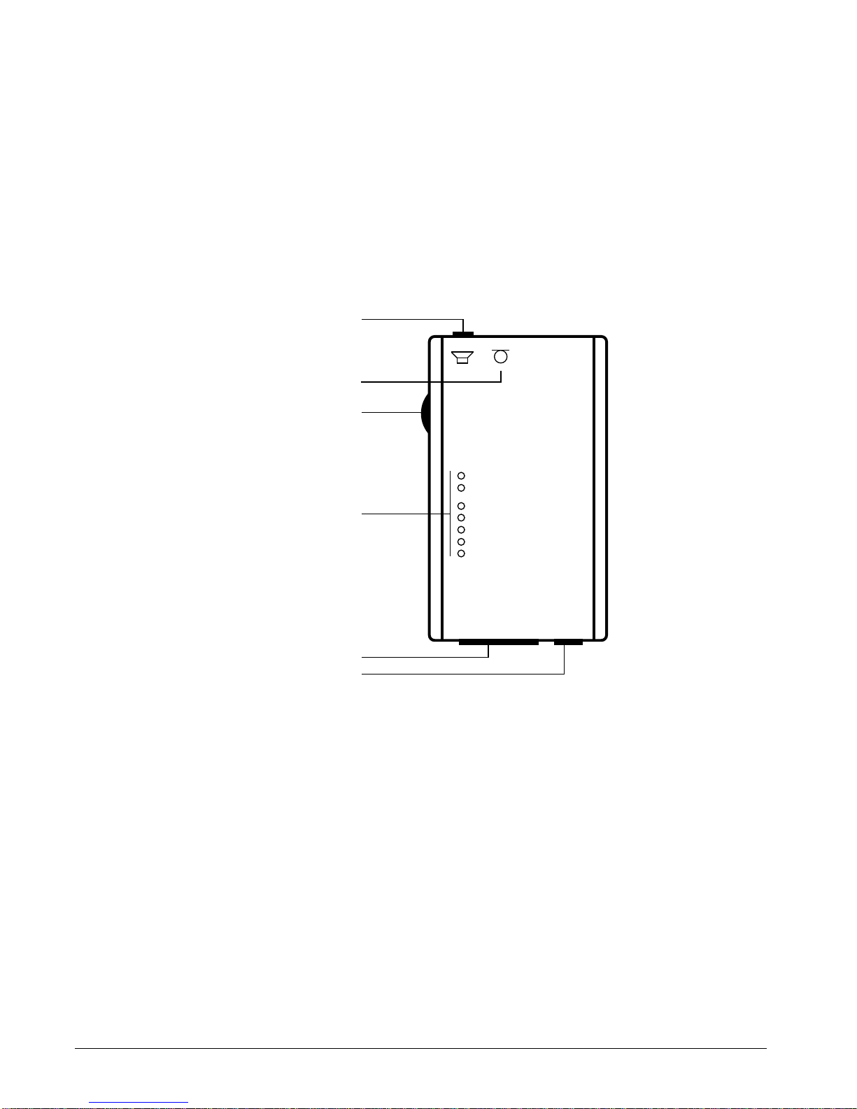
What the LED Indicators mean:
•POWER Modem is ready for operation
•ONLINE Modem is switched to the transmission line
•DSR Answer tone is present
•DCD Modem has recognized the carrier tone from the
remote modem
•CTS Modem is ready to transmit
•RTS Transmission request is present
•DTR Computer is ready for operation
➮Ensure that the correct COM interface is used for the software employed !
POWER
ONLINE
DSR
DCD
CTS
RTS
DTR
Loudspeaker/Headphones
Volume Control
LEDs
COM Interface
Power Supply
Microphone

1-4 INTRODUCTION
Inhaltsverzeichnis
Andere Creatix Modem Handbücher


Beliebte Modem Handbücher anderer Marken

Davicom
Davicom DM562AP Bedienungsanleitung

EpiValley
EpiValley TATA indicom SXC-1080 Bedienungsanleitung

Zte
Zte WiMAX Bedienungsanleitung

Intelimax
Intelimax MA-2060 Bedienungsanleitung

SMC Networks
SMC Networks D3CM1604V Gebrauchs- und Pflegehandbuch

Telstra
Telstra Wi-Fi 4G Advanced Pro X Bedienungsanleitung


US Robotics
US Robotics 3453C Bedienungsanleitung

MaxTech
MaxTech Plug & Play Internal Voice/FAX/Data/SVD... Bedienungsanleitung

Zte
Zte MF823 Bedienungsanleitung

Four-Faith
Four-Faith F1403 Bedienungsanleitung

Sierra Wireless
Sierra Wireless AIRLINK MP595W Bedienungsanleitung

Gemtek
Gemtek WiMAX WIXFBR-103 Bedienungsanleitung