Crestron CHV-RTS Bedienungsanleitung

Crestron CHV-RTS & CHV-RTHS
Remote Temperature/Humidity Sensors
Installation Guide

This document was prepared and written by the Technical Documentation department at:
Crestron Electronics, Inc.
15 Volvo Drive
Rockleigh, NJ 07647
1-888-CRESTRON
All brand names, product names and trademarks are the property of their respective owners.
©2004 Crestron Electronics, Inc.

Crestron CHV-RTS/CHV-RTHS Remote Temperature/Humidity Sensors
Contents
Remote Temperature/Humidity Sensors:
CHV-RTS/CHV-RTHS 1
Introduction......................................................1
Specifications...................................................2
Physical Description ........................................2
Industry Compliance........................................3
Installation .......................................................4
Hardware Hookup............................................5
Problem Solving ..............................................8
Further Inquiries...............................................8
Future Updates .................................................8
Return and Warranty Policies..........................9
Merchandise Returns / Repair Service.............9
CRESTRON Limited Warranty.......................9
Installation Guide - DOC. 8189A Contents •i


Crestron CHV-RTS/CHV-RTHS Remote Temperature/Humidity Sensors
Remote Temperature/Humidity
Sensors: CHV-RTS/CHV-RTHS
Introduction
The CHV-RTS is a remote temperature sensor.
The CHV-RTHS is a remote temperature/humidity sensor.
Both products connect to the Crestron family of remote controlled
thermostat products, which includes two models: CHV-TSTAT and
CHV-THSTAT series. The thermostats are available with and without a
humidity sensor (all thermostats contain a temperature sensor).
Firmware release 1.0 supports the addition of two optional remote sensors
in any combination (two temperature, two temperature/humidity, or one of
each).
Firmware release 2.0 supports the addition of up to four optional remote
sensors, in any combination, for each thermostat.
Outdoor conditions can be imported from the optional external sensors
CHV-RTS or CHV-RTHS, temperature and temperature/humidity
respectively.
Functional Summary
• Small and unobtrusive face allows blending into any décor
• Primed white, may be used as is, painted, or wallpapered
• Easy one-piece mounting (additional hardware not required)
• Readily connects to thermostat with two non-polarized wires
Installation Guide - DOC. 8189A Remote Temperature/Humidity Sensors •1

Remote Temperature/Humidity Sensors Crestron CHV-RTS/CHV-RTHS
Specifications
SPECIFICATION DETAILS
Temperature Range (CHV-
RTS and CHV-RTHS)
-30º to 120ºF (-34.44Cº to
48.89ºC)*
Humidity Range (CHV-
RTHS only)
0 to 100%
*Thermostat front panel indoor temperature display is limited to a range
of 0 – 110ºF (-18º to 43ºC). The front panel outdoor thermostat display
will display the full range of temperature.
Physical Description
Refer to the illustrations below and on the following page.
The face of the sensor is 1.5 in (3.81 cm) wide. The sensor body is 2.22 in
(5.64 cm) long, and mounts nearly flush to the wall.
The CHV-RTS and CHV-RTHS remote sensors are contained in a
cylindrical plastic body with a metal cap. They mount in a one-inch
diameter hole, exposing a 1.5 in (3.81 cm) diameter disk that protrudes
approximately 1/8 in (0.32 cm) from the surface of the wall. Total
mounting depth is about 2.25 in (5.72 cm).
Front and Angled Views
1.59 in
(4.04 cm)
1.50in
(3.81cm)
Mounting Clips
2 •Remote Temperature/Humidity Sensors Installation Guide – DOC. 8189A

Crestron CHV-RTS/CHV-RTHS Remote Temperature/Humidity Sensors
Rear and Angled Views
Pigtail
10 in
(25.40 cm)
22 AWG
Side Views
2.22 in
(5.64 cm)
1/8 in
0.32 cm
Wall
Industry Compliance
As of the date of manufacture, the CHV-RTS/CHV-RTHS have been
tested and found to comply with specifications for CE marking and
standards per EMC and Radiocommunications Compliance Labelling
(N11785).
NOTE: This device complies with part 15 of the FCC rules. Operation is
subject to the following two conditions: (1) this device may not cause
harmful interference, and (2) this device must accept any interference
received, including interference that may cause undesired operation.
Installation Guide - DOC. 8189A Remote Temperature/Humidity Sensors •3

Remote Temperature/Humidity Sensors Crestron CHV-RTS/CHV-RTHS
Installation
1. Ensure that the location is not close to a heat or humidity source and
away from direct sunlight, skylights, and windows. When mounting
the sensor outdoors, do not place in direct sunlight, and do not place
where the sensor will be directly exposed to precipitation. Sensors are
suitable for mounting in dry or damp locations as defined by the
National Electrical Code.
2. Locate an area on the wall that is free of miscellaneous wiring and
studs.
3. Make a small hole near the center of the designated mounting site to
verify that the location is suitable.
4. Drill or cut a 1 in (2.54 cm) diameter circular hole in the wall at the
desired position.
5. Route the wires from the thermostat to the sensor. For thermostat
connection details, refer to the latest version of Crestron CHV-TSTAT
& CHV-THSTAT Thermostats Operation and Installation Guide,
Doc. 8163.
NOTE: Crestron strongly recommends low-capacitance twisted pair wire
such as CAT3 (up to 250 ft, 76.2 m) or CAT5 (up to 500 ft, 152.4 m)
network cable when using remote sensors. Maximum distance from
sensor to thermostat is 500 ft, 152.4 m
If multi-conductor cables are used, the leftover conductors must NOT be
used for other purposes and must be left unconnected at both ends.
In situations where ordinary two-conductor thermostat wire (18 to 20
gauge) has been installed, it may be used for runs up to 100 feet (30.48
meters). This is not a preferred method of installation.
Other cable types are satisfactory, provided the total capacitance is less
than 7000 pF.
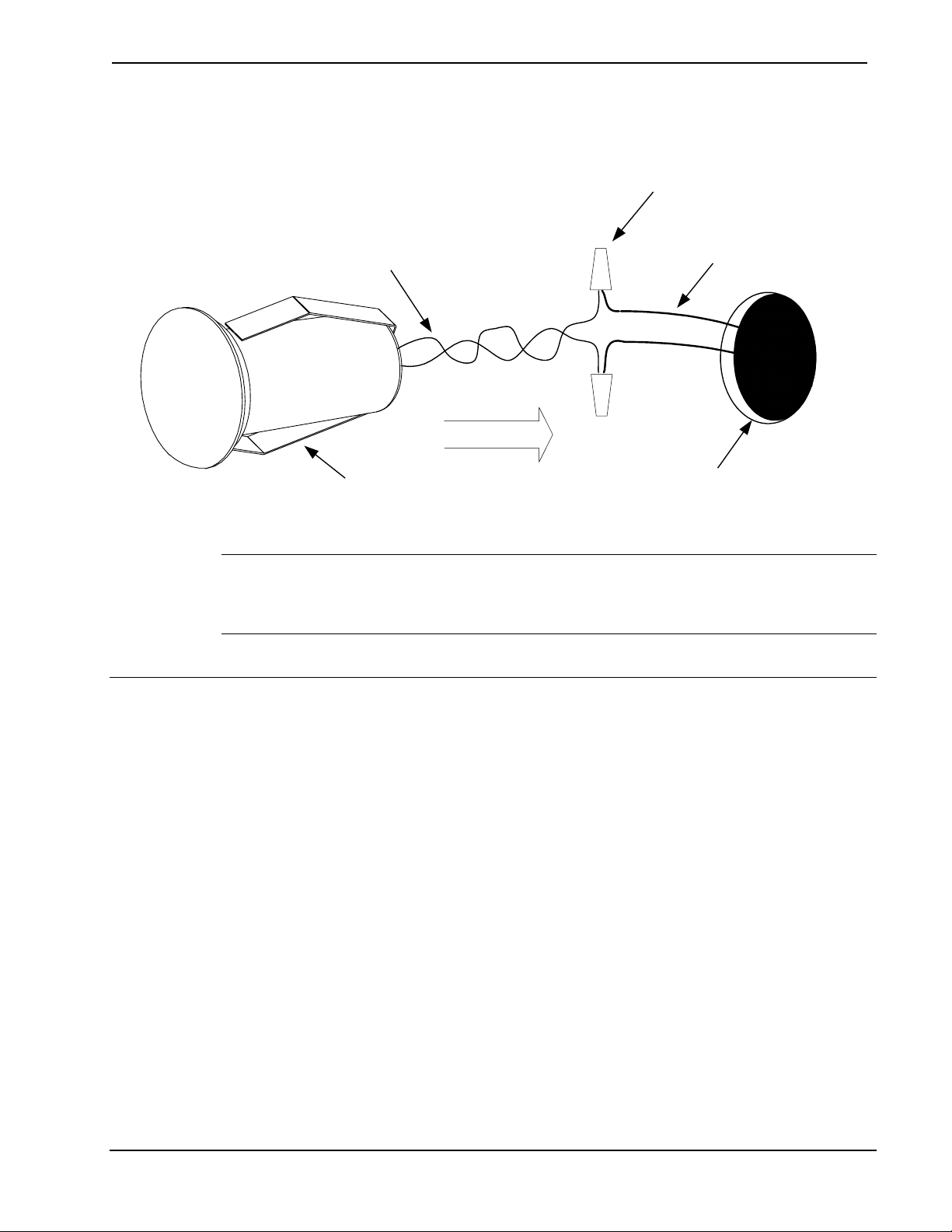
6. Connect the wires from the thermostat to the 10 in (25.4 cm) sensor
pigtail (22 AWG x12" black/black twisted pair) using wire nuts. The
wires are non-polarized. (Refer to “Hardware Hookup” on page 5).
4 •Remote Temperature/Humidity Sensors Installation Guide – DOC. 8189A
Crestron CHV-RTS/CHV-RTHS Remote Temperature/Humidity Sensors
7. Press fit the sensor into the hole; the clips on either side of the sensor
hold it in place.
Pigtail Wires from Sensor
1in (2.54cm) Hole
Mounting Clips
Wires from Thermostat
Wire Nuts
NOTE: The face of the sensor may be painted or wallpapered to match
the wall. However, keep the small gap around the outer edge clear of any
obstructions.
Hardware Hookup
The sensors are connected to the remote sensor terminals RS1, RS2, and a
common connection RSR on the rear plastic housing of the thermostat.
Separate the thermostat from its backplate. The thermostat terminal blocks
mate to pins protruding out of the front thermostat assembly.
Thermostat firmware release 1.x supports the addition of only two
optional remote sensors (temperature and/or temperature/humidity) per
thermostat on sensor inputs RS1 and RS2.
Thermostat firmware release 2.x supports up to four optional temperature
(CHV-RTS) or slab sensors (CHV-RSS) or two temperature/humidity
sensors (CHV-RTHS).
If you are using one temperature/humidity sensor, then you may add two
temperature sensors (CHV-RTS or CHV-RSS) to the other sensor input.
Installation Guide - DOC. 8189A Remote Temperature/Humidity Sensors •5

Remote Temperature/Humidity Sensors Crestron CHV-RTS/CHV-RTHS
Connection Example 1: Connecting two temperature/humidity sensors to
the thermostat (maximum number of temperature/humidity sensors):
NOTE: Sensor wiring is non-polarized
1. Remote sensor 1 connected to RS1 and RSR
2. Remote sensor 2 connected to RS2 and RSR
TOP
HUM
RHU
RSR
RSR
RS1
RS2
24(C)
24(R)
24V
Y
Z
G
NETWORK
Remote Sensor 1
Remote Sensor 2
Thermostat Back
p
late
Connection Example 2: Connecting four temperature sensors
(CHV-RTS) to the thermostat (maximum number of temperature sensors):
1. Remote Sensor 1 and 3 are connected to RS1 and RSR.
2. Remote Sensor 2 and 4 are connected to RS2 and RSR.
TOP
HUM
RHU
RSR
RSR
RS1
RS2
24(C)
24(R)
24V
Y
Z
G
NETWORK
Remote Temperature Sensor 1
Remote Temperature Sensor 2
Remote Temperature Sensor 3
Remote Temperature Sensor 4
Thermostat Back
p
late
6 •Remote Temperature/Humidity Sensors Installation Guide – DOC. 8189A
Andere Handbücher für CHV-RTS
1
Dieses Handbuch passt für folgende Modelle
1
Inhaltsverzeichnis
Andere Crestron Temperaturregler Handbücher


Beliebte Temperaturregler Handbücher anderer Marken

Swegon
Swegon LUNAd MB Bedienungsanleitung

Lucky Reptile
Lucky Reptile Thermo Control II Bedienungsanleitung

SENSORMETRIX
SENSORMETRIX Argon 100 Bedienungsanleitung

Fuji Electric
Fuji Electric PXE4 Bedienungsanleitung

Yuyao gongyi
Yuyao gongyi XMT-808 series Bedienungsanleitung

Selec
Selec TC544C Bedienungsanleitung


