Cub Cadet CC924 Bedienungsanleitung

OPERATOR’S MANUAL
WARNING
READ AND FOLLOW ALL SAFETY RULES AND INSTRUCTIONS IN THIS MANUAL
Safe Operation Practices Set-Up Operation Maintenance Service Troubleshooting
BEFORE ATTEMPTING TO OPERATE THIS MACHINE.
FAILURE TO COMPLY WITH THESE INSTRUCTIONS MAY RESULT IN PERSONAL INJURY.
·
FORM NO. 769-11081 02
01/25/2018
· · · ·
Brushcutter CC924/CC927D/CC927U
2
Safety Instructions..........................................3
Visit us on the web at www.mtdproducts.com
Contact MTD AU • P.O. Box 376 Dandenong.Vic.3175
Email Address: [email protected] Customer Service Phone:1300 951 594
Symbols...........................................................5
Get to know yur brush cutter.........................7
Assembly Instructions....................................9
Fuel and Oil Instructions..............................11
OperatingInstructions.................................12
Maintenace and repair.................................14
Cleaningand Storage..................................17
Tro
Contents ....................................................... 20
ubleshooting...........................................18
19
Before setting up and operating your new equipment,
please locate the model plate on the equipment and record
the information in the provided area to the right. You can
locate the model plate on the engine of the brushcutter
This information will be necessary, should you seek technical
support via our web site, Customer Support Department,
or with a local authorized service dealer.


18. The rotary spool head and/or the cutting blade may keep running for a short time just after
your shutting it down. Always be aware of the rotating parts; they are dangerous. If the
cutting attachments cannot stop at idling, you should adjust the carburetor.
19. Never use parts, accessories or attachments which are not authorized for this unit. Otherwise,
the user may be seriously injured and/or the unit damaged and the warranty may be deemed
null and void.
20. If situations occur which are not covered in this manual, please contact MTD customer service
department or your nearest local dealer.
4

Indicates danger,warning or a reason to be cautious.Can be used together with
other symbols or pictograms.
SAFETY AND WARNING SYMBOL
Non-compliance with the operating instructions and precautions may result in
serious injuries.Read the operating manual before starting or operating the unit.
READ OPERATING MANUAL
CAUTION: Ejected objects may cause serious eye injuries and excess noise may
cause loss of hearing.When operating the unit,wear eye and ear protection.
WEAR EYE AND EAR PROTECTION
CAUTION: All bystanders,especially children and pets,must be kept at
least 15m from the working area.
KEEP BYSTANDERS AWAY
Always use clean and fresh lead-free petrol for mixing petrol.
PETROL
Use only authorised oil according to the operating manual for mixing petrol.
OIL
Keep hands and feet away from rotating parts.
CAUTION: Do not use the unit if the protective housing has not been correctly
positioned for cutting.Keep away from the rotating line coil.
EJECTED OBJECTS AND ROTATING PARTS MAY CAUSE SERIOUS INJURIES
SYMBOLS
5

RUN
OFF/STOP
IGNITION SWITCH
BEWARE OF HOT SURFACES
CAUTION
SHARP BLADE
MAXIMUM RPM
9000
IGNITION SWITCH
GLOVES
Please wear sturdy gloves.
SHOES
Please wear afety shoes.
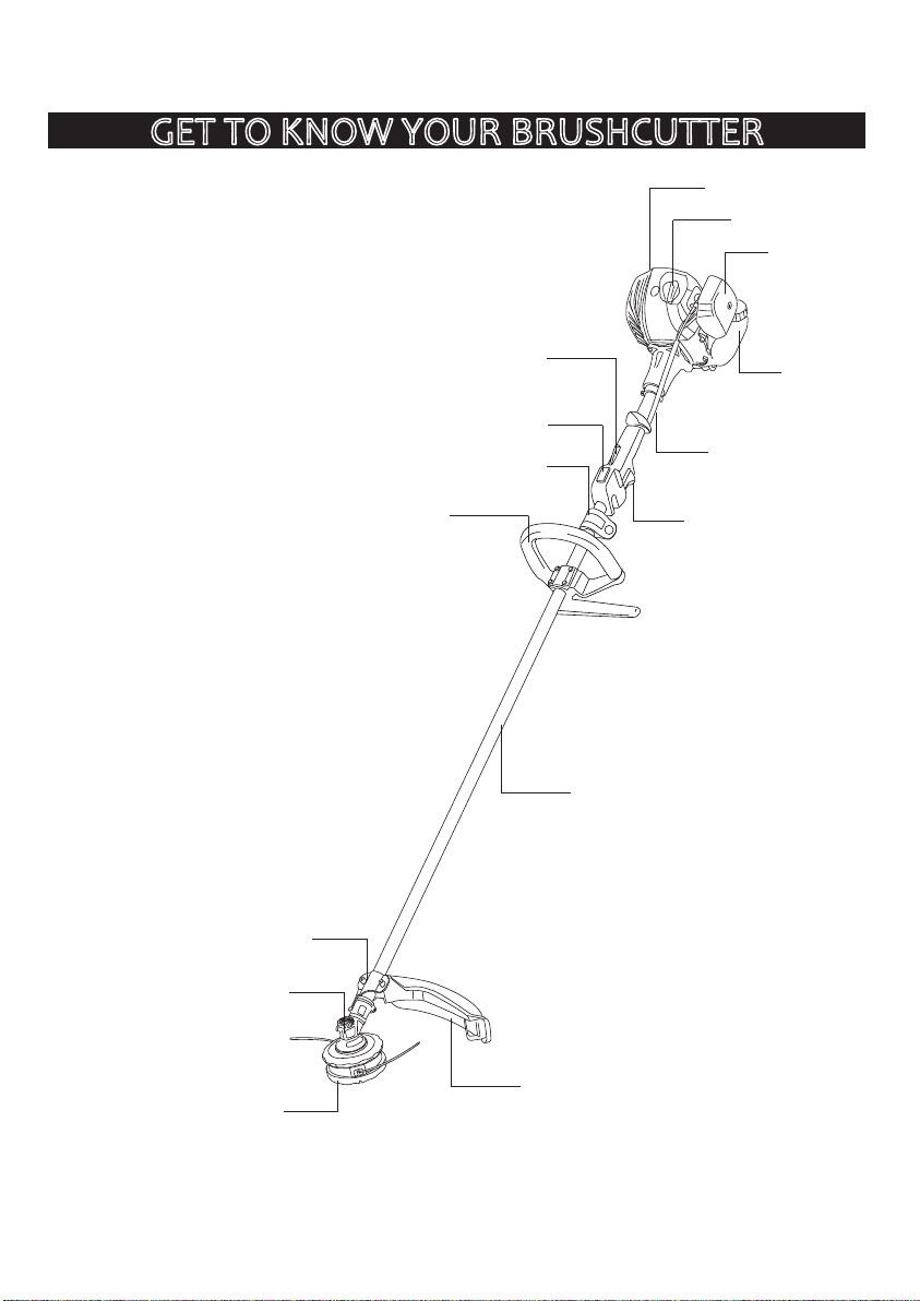
Gear Case
Cutting Attachment Shield
Shaft Tube
Clamping Bracker For
Cutting Attachment Shield
D-Handle
Air Filter Cover
Fuel Tank
Ignition Switch
Throttle Trigger
Throttle Lockout
Spark Plug Cap
Throttle Cable
Trimmer Head
GET TO KNOW YOUR BRUSHCUTTER
7
Muffler Cover
Brushcutter with “D” Handle
Harness Bracket

Gear Case
Cutting Attachment Shield
Shaft Tube
Clamping Bracket For
Cutting Attachment Shield
U-Handle
Air Filter Cover
Fuel Tank
Ignition Switch
Throttle Trigger
Throttle Lockout
Throttle Cable
Harness Bracket
Spark Plug Cap
Throttle Cable Collector
Trimmer Head
8
Muffler Cover
Clamping Bracket For U-Handle
Brushcutter with “Bull” Handle
GET TO KNOW YOUR BRUSHCUTTER

INSTALL AND ADJUST HANDLE
.
ASSEMBLY INSTRUCTIONS
9
INSTALL THE CUTOFF KNIFE
1. Align the knife hole with the hole on shield,
then tighten them up with screws.
Cutoff Knife Cutting Attachment
Shield
Screw
Align the two holes on the cutting attachment
shield with the other two holes in the clamping
bracket, then tighten them up with screws.
INSTALL THE CUTTING ATTACHMENT SHIELD
Cutting
Attachment
Shield
Screw
Clamping
Bracket
1. Push the handle down onto the tube,and
set the lower handle into the right place,
so that the parts matched right.
2. Insert the bolt into the bolt hole and push
it through.and put the nut into the nut hole
on the lower handle back.tighten the bolt,
but do not tighten the bolt completely.
3. While holding the unit in the operation,
move the handle to the location that
provides the best grip. Place it a minimum
of 6 inches(152mm) from the end of the grip.
make sure the handle base between arrows.
4. Tighten the bolt until the handle is secure.
D-Handle
Lower Handle
152mm
2. You can adjust the operating angles of the
handle by loosening the handle locking knob.
1. Put the “Bull” Handle between the top and
middle clamps, and then connect the top,
middle and bottom clamps by tightening
the handle locking knob.
U-Handle
Middle Clamp
Bottom Clamp
Locking Knob
Washer
Top Clamp
“D” Handle
“Bull” Handle

10
3. Install the blade holder and blade holder
cover one by one.
4. Finally, install the locking nut and tighten
it by the hex wrench.
INSTALL THE CUTTING BLADE(if attached)
1. Align the shaft bushing hole with the locking
rod slot in the protective cover and the notch
in the gear case, and then insert the locking
rod into these three holes/slots. Holding the
locking rod to ensure the output shaft in
place.
2. Install the blade to the output shaft and
make sure it contacts closely with the shaft
busing.
Blade Holder Cover
Shaft Bushing
Locking Nut
Blade Holder
Blade Holder Cover
Wrench Clockwise
Locking Rod
Gear case
INSTALL THE TRIMMER HEAD
1. Align the shaft bushing hole with the locking
rod slot in the protective cover and the
notch in the gear case, and then insert the
locking rod into these three holes/slots.
Holding the locking rod to ensure the output
shaft in place.
2. Ensure the threads of the trimmer head and
the center of the output shaft are in line
with each other, and then rotate the trimmer
head clockwise (observed by operator) until
it is securely tightened.
Output Shaft
Protective Cover
Locking Rod
Gear case
Clockwise
Dieses Handbuch passt für folgende Modelle
2
Inhaltsverzeichnis
Andere Cub Cadet Freischneider Handbücher


