Cumberland SPRKT2415 Technisches Datenblatt

PNEG-881
Curtain Controller
Sprocket and Chain Drive
Featuring the Header Sprocket System
Operation and Installation Manual
PNEG-881
Date: 03-09-09

2PNEG-881 Curtain Controller
This equipment shall be installed in accordance with the current installation codes and
applicable regulations which should be carefully followed in all cases. Authorities having
jurisdiction should be consulted before installation occurs.

Table of Contents
PNEG-881 Curtain Controller 3
Contents
Chapter 1 Safety.................................................................................................................................................. 4
Safety Guidelines ............................................................................................................................... 4
General Safety Statement ................................................................................................................. 5
Chapter 2 Decals................................................................................................................................................. 7
Chapter 3 Installation ......................................................................................................................................... 9
Chapter 4 Header Sprocket/Pulley .................................................................................................................. 12
Header Sprocket or Pulley Configurations ....................................................................................... 12
Chapter 5 Sprocket/Pulley Cover Mounting................................................................................................... 13
Sprocket/Pulley Cover Mounting Instructions .................................................................................. 13
Chapter 6 Maintenance..................................................................................................................................... 14
Chapter 7 Troubleshooting Guide................................................................................................................... 15
Chapter 8 Parts List.......................................................................................................................................... 17
Enclosed Limit Switch Assembly (SPRKT2430 and SPRKT2460 Only) ......................................... 17
Enclosed Limit Switch Assembly (All Other Sprocket Machines) .................................................... 18
Curtain Machine Components ......................................................................................................... 20
Chapter 9 Installation Kit.................................................................................................................................. 24
AC180-A Installation Kit (Purchased Separately) ............................................................................ 24
AC180-B Installation Kit (Purchased Separately) ............................................................................ 25
Chapter 10 Wall Mount..................................................................................................................................... 27
Outside Endwall Mount for Curtains .............................................................................................. 27
Outside Sidewall Mount for Curtains (Vertical Installation) ............................................................ 28
Inside Endwall Mount for Curtains ................................................................................................. 29
Inside Sidewall Mount for Vent Doors (Vertical Installation) .......................................................... 29
Inside Endwall Mount for Vent Doors (Vertical Installation) ........................................................... 30
Inside Sidewall Mount for Vent Doors (Horizontal Installation) ...................................................... 30
Chapter 11 Wiring Diagrams............................................................................................................................ 31
Wiring Diagram for 110V 60 Hz ..................................................................................................... 31
Wiring Diagram for 220V 50/60 Hz ................................................................................................ 32
Chapter 12 Warranty......................................................................................................................................... 33

4PNEG-881 Curtain Controller
1. Safety
Safety Guidelines
This manual contains information that is important for you, the owner/operator, to know and understand.
This information relates to protecting personal safety and preventing equipment problems. It is the
responsibility of the owner/operator to inform anyone operating or working in the area of this equipment
of these safety guidelines. To help you recognize this information, we use the symbols that are defined
below. Please read the manual and pay attention to these sections. Failure to read this manual and its
safety instructions is a misuse of the equipment and may lead to serious injury or death.
This is the safety alert symbol. It is used to alert you to
potential personal injury hazards. Obey all safety
messages that follow this symbol to avoid possible
injury or death.
WARNING indicates a potentially hazardous situation
which, if not avoided, could result in death or serious injury.
CAUTION indicates a potentially hazardous situation which,
if not avoided, may result in minor or moderate injury.
CAUTION used without the safety alert symbol indicates a
potentially hazardous situation which, if not avoided, may
result in property damage.
NOTE indicates information about the equipment that you
should pay special attention.
DANGER indicates an imminently hazardous situation
which, if not avoided, will result in death or serious injury.

1. Safety
PNEG-881 Curtain Controller 5
General Safety Statement
Our foremost concern is your safety and the safety of others associated with grain handling equipment.
This manual is to help you understand safe operating procedures and some problems which may be
encountered by the operator and other personnel.
As owner and/or operator, you are responsible to know what requirements, hazards and precautions
exist and inform all personnel associated with the equipment or in the area. Safety precautions may be
required from the personnel. Avoid any alterations to the equipment, which may produce a very
dangerous situation, where SERIOUS INJURY or DEATH may occur.
Electrical Safety
An adequate and safe power supply to the Curtain Controller unit is essential for safety. A competent
and qualified electrician must undertake all electrical wiring. All wiring is to be installed according to the
National Standards and Regulations relevant to your Country and Region.
Electrical safety devices, emergency stop and main isolators are provided with the Curtain Controller
System and are essential for safety. This should be installed as indicated in the enclosed installation
instructions and in accordance with the relevant codes and directives.
User’s Manual
This manual contains information and instructions essential to the safe installation and use of the
Curtain Controller System. Read this manual thoroughly before attempting any installation or use
of the Curtain Controller System. Keep this manual with the Curtain Controller System or in a location
where it can be readily accessed. Failure to read this manual and its safety instructions is a misuse
of the equipment.
Correct Uses of Your Curtain Controller
The Curtain Controller System is designed solely for the purpose of controlling vent doors in livestock
(swine and chicken) houses. Use of the system in any other way is a misuse of the system and may
endanger safety and health.
Only genuine AP/Cumberland parts are to be used in the installation and use of the
Curtain Controller
System. Use of other non-genuine parts is a misuse of the system andmay lead to dangerous situations
imperilling the safety and health of you and others.
Controls
TheCurtainControllerisdesignedforusewithmanualor automatictemperaturecontrol.GSIrecommends
the use of genuine GSI controls. Use of any controllers that do not meet this specification can pose a risk
to health and safety and will lead to malfunction and failure of the Curtain Controller.
This machine is not designed for use in atmospheres where there is a risk of explosion. Use of the Curtain
Controller System in such an environment is prohibited. If in doubt, contact your dealer or GSI.
Safety Guards
TheCurtainController Systemcontainsmanymovingand electrical parts,whichwillcauseserious injury
or death if touched. Guards are placed on the machine for your protection. Operating the machine
at any time with guards removed or incorrectly fitted is a serious misuse of the machine and
endangers safety.

1. Safety
6PNEG-881 Curtain Controller
Safety in Handling the Curtain Controller System
The Curtain Controller weights:
All precautions should be taken when lifting and/or moving the unit, to prevent the risk of physical injury.
Maximum Load
The Curtain Controllers with 15 RPM and 30 RPM gear motors can lift a maximum of 4000 lbs/1814 kg
at a 1:2 pulley ratio. 60 RPM Gear motors can lift a maximum of 1000 lbs/453 kg at a 1:2 pulley ratio.
Safety in Maintenance
While the Curtain Controller is designed to keep maintenance to a minimum, some maintenance will be
necessary in the course of the life of the machine. Do not attempt any repairs on the machineunless you
are competent to do so. Remember that the Curtain Controller may operate under automatic control and
start without warning. Never attempt any work on the Curtain Controller without first isolating the
machine from the main power and locking the isolator so that only you can turn the power back ON.
Follow all guidelines given in the maintenance section of this manual.
Before restarting the Curtain Controller, ensure that all electrical enclosures are locked closed and all
guards and other safety measures are correctly fitted.
If in any doubt, contact your dealer or GSI for assistance.
Noise
Tests on this machine indicate noise levels at a position one (1) meter from the drive unit, and 1.6 meters
above the ground do not exceed 70 dBa, continuous “A” weighted sound pressure or 63 Pa,
instantaneous “C” weighted sound pressure.
Model # Weight
SPRKT2415
104 lbs/47 kgSPRKT2430
SPRKT2460
SPRKT3615
119 lbs/54 kgSPRKT3630
SPRKT3660
SPRKT4815
135 lbs/61 kgSPRKT4830
SPRKT4860
SPRKT6015
151 lbs/69 kgSPRKT6030
SPRKT6060

PNEG-881 Curtain Controller 7
2. Decals
Safety Decals and Warnings
The following pages show you exactly where the safety signs and warnings (decals) should be placed
on your Curtain Controller. If a decal is missing, damaged or unreadable, please contact your dealer or
the GSI group, for a free replacement.
For guidance or assistance on any issues relating to the safe use of the Curtain Controller System,
Contact:
GSI Group
1004 E. Illinois St.
Assumption, IL. 62510
Phone: 217-226-4421
Fax: 217-226-4420
Decal-889 is located above the electrical box on
the outside of the Curtain Controller.
DC-889 is located on the electrical unit within the
Curtain Controller.

2. Decals
8PNEG-881 Curtain Controller
DC-856 is located on the sides of the Curtain
Controller underneath the sprocket covers.
DC-1517 is located underneath the sprocket
covers above the warning decal (DC-856) on the
Curtain Controller.
WARNING
DC-856
Moving parts can
crush and cut.
Keep hands clear of
sprocket and chain.
DC-1516 is located on the front cover of the
Curtain Controller.
Automatic equipment.
May start at any time.
Lockout power before
servicing.
DC-1516

PNEG-881 Curtain Controller 9
3. Installation
This manual outlines the recommended sequence for the installation of the Curtain Controller System.
Following the sequence will prove the safest and easiest method ofinstallation. Above all, connection of
the system to the electrical mains should be final stage of installation. Failure to observe this could lead
to a fatal accident.
1. Unpack the Curtain Controller and remove the front cover. Inspect the machine for visible defects.
2. Select mounting configuration. (See examples of: Outside sidewall one (1) curtain, outside endwall
two (2) curtains and inside endwall two (2) curtains on Page 27-30.)
3. Screw one (1) 3/8" x 3" lag bolt 6-1/2" below the desired height of the Curtain Controller.
NOTE: Leave 1-1/2" between the bolt head and the wall. (See Figure 3A.)
Figure 3A
4. Using the “keyhole” slot in the back of the Curtain Controller, hang the machine on the 3" lag bolt.
(See Figure 3B.) NOTE: The 3" lag bolt should only be used to hang the machine to the wall. Do
not attempt to operate the machine until it is fully secured.
Figure 3B
3. Installation
10 PNEG-881 Curtain Controller
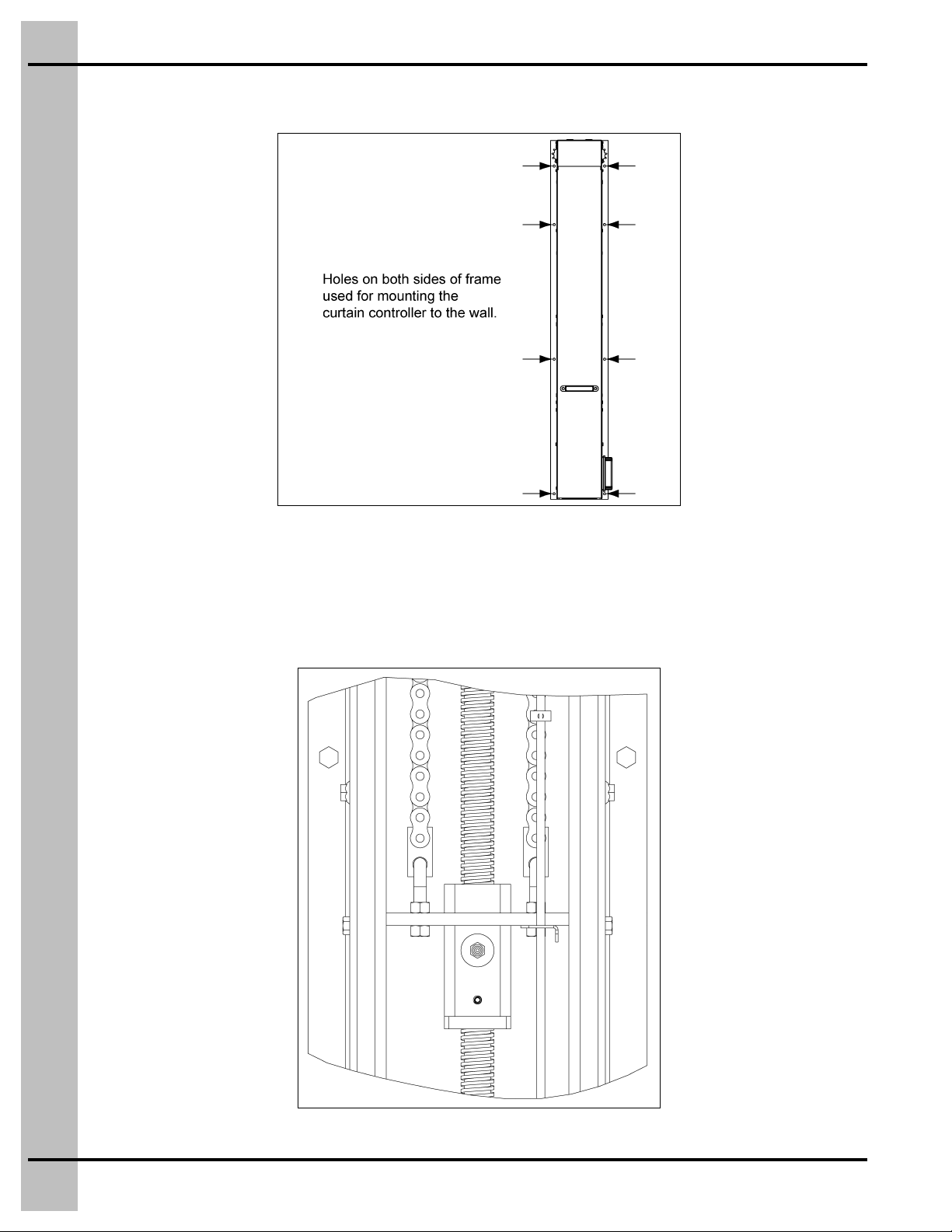
5. Secure the machine to the wall by using the minimum six (6) 3/8" x 2" lag bolts provided.
(See Figure 3C.)
Figure 3C
6. Remove pulley/sprocket covers.
7. Insert the chain into the top of the machine onto the sprocket and pull down through the machine
until the chain reaches the chain adapter. (See Figure 3D.)
8. Fasten the chain to the chain adapter by using the master link. (See Figure 3D.)
Figure 3D
Dieses Handbuch passt für folgende Modelle
11
Inhaltsverzeichnis
Andere Cumberland Controller Handbücher

Cumberland
Cumberland PNEG-881 Bedienungsanleitung

Cumberland
Cumberland Evolution 4000 Bedienungsanleitung

Cumberland
Cumberland EDGE 2 Bedienungsanleitung

Cumberland
Cumberland EDGE 074-11793 Kurzanleitung

Cumberland
Cumberland Smart-Flex FLX-4629 Bedienungsanleitung

Cumberland
Cumberland Evolution 1200 Series Bedienungsanleitung

Cumberland
Cumberland 891-00516 Bedienungsanleitung

Cumberland
Cumberland Evolution 3000 Bedienungsanleitung

Cumberland
Cumberland Evolution Back-Up Bedienungsanleitung

Cumberland
Cumberland Evolution S3 Bedienungsanleitung


