ROBOT . HEAD to TOE
Product User’s Manual – G15 Shield R2
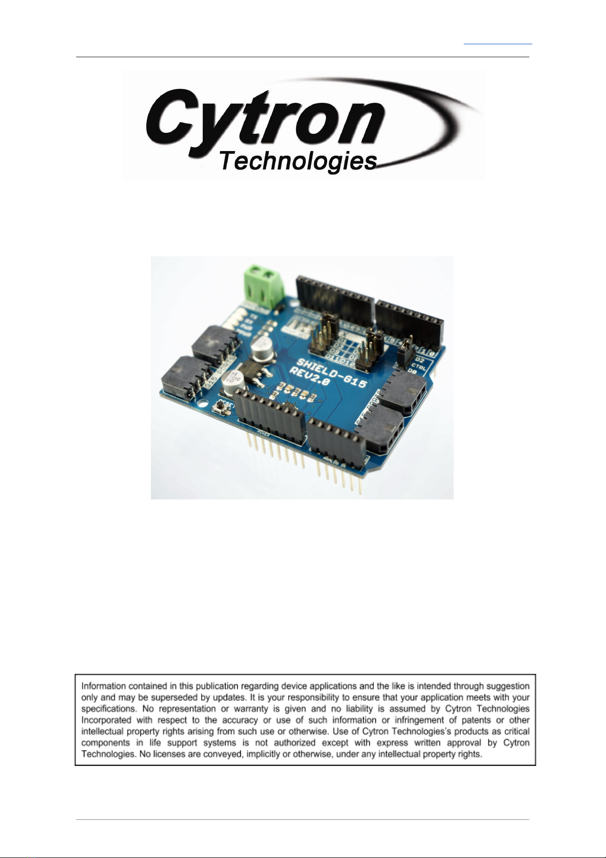
1.0 INTRODUCTION
G15 Shield is an Arduino shield for controlling Cytron’s G15 Cube Servo. It converts UART
duplex communication to half-duplex single line communication compatible for G15 Cube
Servo. It is compatible with Arduino Uno,Arduino Duemilanove,Arduino Mega2560,
Arduino Leonardo and possibly other pin compatible main boards.
G15 Shield Rev2.0 has four ports for Cytron’s G15 Cube Servo. The two ports for Robotis’
Dynamixel AX-12 servo were removed from G15 Shield. G15 Cube Servo is serial servo
which can be daisy chained for more servos. G15 Shield has external motor power port for
user to supply separate power for the servos besides using the internal power from the
Arduino board. G15 Shield has stackable side headers which allows for more Arduino shields
to be stacked on top of it.
G15 Shield R2 comes with:
●Arduino Reset button.
●4 x G15 Cube Servo ports, two extra on Rev2.0.
●G15 control pin selector (D2 or D8).
●External power port for servo with polarity protection.
●Stackable I/O header pin.
●Selectable Digital pins for UART communication with G15, via mini jumpers.
●2 LEDs as logic power and servo power indicators.
●TX and RX LED indicators, new on Rev2.0.
●On pad internal and external power selectable.
Created by Cytron Technologies Sdn. Bhd. – All Right Reserved 3