
d.s.f. BZ - V 24 TK Bedienungsanleitung
Internationales Know-How in der Flammenüberwachung
International Know-How in Flame Detection
Operating Instructions
Portable Burner Igniter
BZ – V 24 TK

d.s.f. GmbH BZ – 24 TK ersion 11/2021 Page
2 of 10
Table of Contents
Table of Contents
1. Description of the igniter 3
1.1. Technical data of the igniter 3
1.2. Casing configuration 4
1.3. Connection of the battery charger at the appliance inlet 4
2. Operating principle 5
3. Start-up 5
4. Battery charger 6
4.1 Technical data of the battery charger 6
5. Faults & break-downs 7
6. Repairs 7
6.1. Replacing the high-energy-spark plug 7
6.2. Replacing the spark plug connector and the high-voltage cable 8
6.3. Replacing the spark gap 8
7. Maintenance 9
8. Spares 9
8.1. Spare part list 9
9. Delivery conditions 10
10. Storage 10
11. Warranty 10

d.s.f. GmbH BZ – 24 TK ersion 11/2021 Page
3 of 10
1. Description of t e igniter
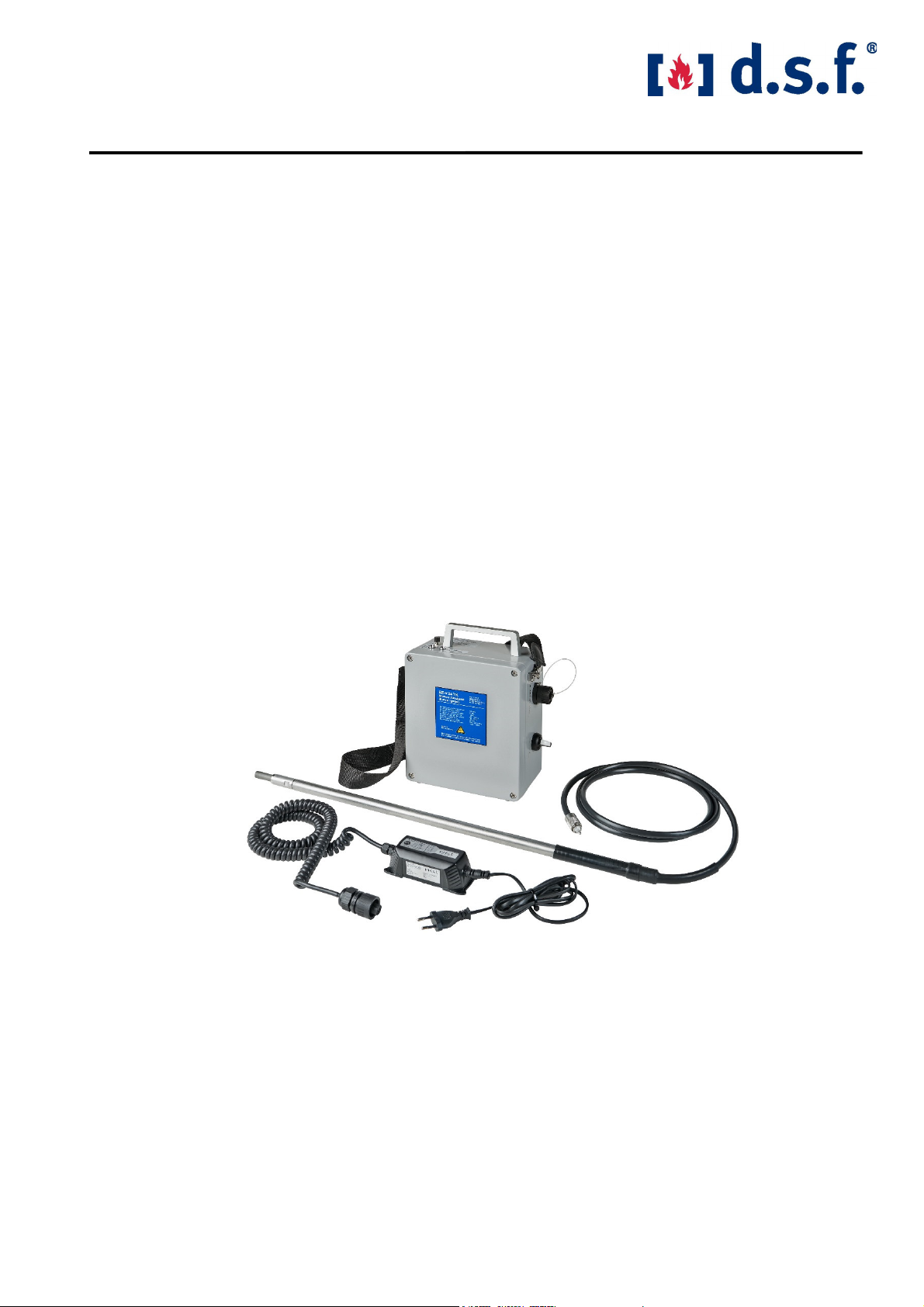
The portable burner igniter type BZ – 24 TK has been designed for the safe ignition of gas and
oil burners, as requested by practical considerations. It consists of an aluminum die-cast casing
with handle, push-button and carrying strap, the latter housing the power electronics as well as two
maintenance-free, closed lead-acid batteries. These batteries are suitable for applications with fre-
quent charging/discharging cycles. To protect battery lifetime, an additional LED will show the low
state of charge.
The high-energy spark plug with the plug extension has a handle. The high-voltage cable is tightly
connected with the ignition lance and, via a plug-in connector, with the electronic module. The
operating voltage will be fed in thru the control switch underneath the appliance inlet for connecting
the battery charger, and the igniter will be activated by pressing the push-button (please observe
the start-up instructions!). A yellow-LED installed there will indicate the ignition function.
1.1. Tec nical data of t e igniter:
Operating voltage: 24 DC
Ignition voltage: 1 600
Ignition frequency: 25 Hz … 30 Hz
Maximum continuous ignition: 2 min (ED 66%)
Battery: Lead-acid batteries in dryfit technology, electrolyte acc. to
DIN 43534
oltage: 2 x 12
Nominal capacity: 1.2 Ah each
Charging time: Approx. 4 hours
Weight: 5.3 kg
Degree of protection: IP 65
Casing: Aluminum die-cast casing, color RAL 7001 gray
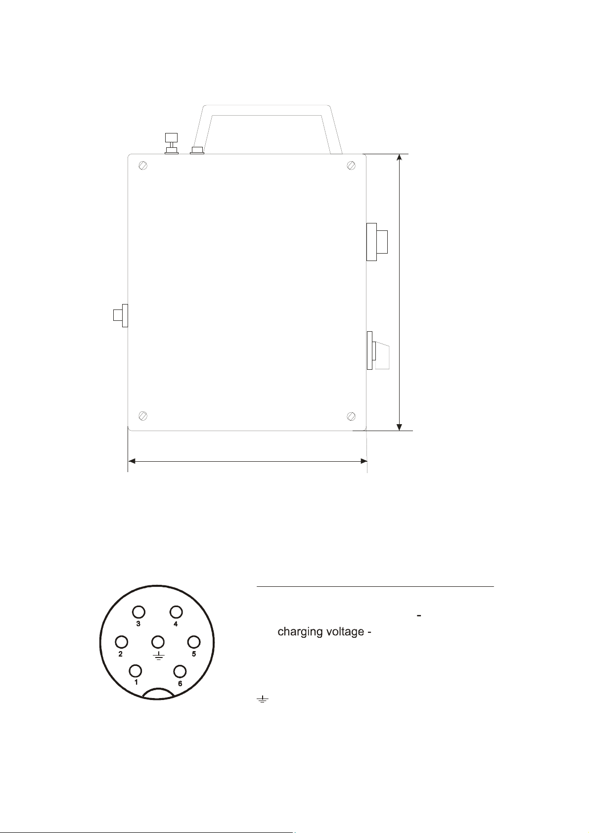
Dimensions: (w x h x d) 200 x 230 x 110 mm (Fig. 1)
Ambient temperature: -15 … +60° C
Spark plug temperature: 480° C, briefly 800° C
Useful life spark plug: 10
6
sparks (approx. 12 hrs. ignition time with 25 sparks/sec)
Ignition energy: 30-37,5 Joule per second, depending on the battery charging
Ignition lance diameter: 18 mm
Ignition lance length: Supply according to plant requirements (customized)
d.s.f. GmbH BZ – 24 TK ersion 11/2021 Page
4 of 10
1.2 Casing configuration
Fig. 1
200
230
1.3 Connection of t e battery c arger at t e appliance inlet
Fig. 2
1
2
3
4
5
6
protective conductor PE
-
green/yellow
free
charging voltage +
free
free
free
blue
brown
-
-
soldering wire
connection strand marking

d.s.f. GmbH BZ – 24 TK ersion 11/2021 Page
5 of 10
2. Operating principle
The operating voltage will be transformed to 1.6 k , so that a capacitor can be charged. Once the
above voltage is reached, a spark gap in the casing becomes conductive, while the capacitor is
being discharged via the high-energy spark plug. Thus, a light arc with high energy content is
generated. The electronic system is dimensioned in such a way that a discharge frequency of
approx. 25 Hz will be generated. The energy content of the spark as well as the high ignition fre-
quency will facilitate the problem-free ignition of the fuel-air mixture in the burner. The igniter is
designed short-circuit-proof and secured against surge voltages. Should the appliance be started
with an open discharge circuit or with a faulty high-energy spark plug, the operating voltage will be
automatically cut off and the appliance be blocked. A re-start is only possible by switching off the
operating voltage (with the push-button being released). An ON time of 66 % is possible, despite
the high currents that flow during the ignition process.
3. Start-up
You have to charge the battery before the first startup!
Before starting the igniter, check the physical condition of the ignition lance and, especially, of the
ignition cable. Should a cable plug or its insulation be damaged, the appliance must not be used.
If the red LED is on, the discharge voltage is reached and the startup to be omitted and the batteries
to be recharge immediately. The igniter must only be started with the ignition lance inside the
burner.
Operating outside of t e burner is not allowed!
The appliance shall be started in the very place, where it is supposed to be used. In order to start
the appliance, connect the high-voltages cable of the ignition lance with the igniter’s high-voltage
(H ) socket. A Equipotential bonding must be established between the grounding bolt on the igniter
and the burner. The equipotential bonding line should be at least a 4 mm² cable.
Position the spark plug at the burner close to the fuel emitted from the burner nozzle.
Then turn on switch S1 underneath the appliance inlet for the battery charger. The igniter is actually
started by pressing the push-button next to the carrier handle. An internal circuit will signal via the
indicator light installed in the appliance that the igniter is ready for operation. An intensive light arc
will become visible at the high-energy spark plug. The fuel inlet can now be opened. The energy
content and the high ignition frequency will facilitate a problem-free ignition of the fuel-air mixture.
After the flame has appeared, the igniter can be deactivated, while the lance should be speedily
removed from the flame area (with the spark plug’s admissible temperature being observed!) and
the spark plug should not be touched. The plug’s retention time in the flame will generate temper-
atures than can cause burns.

d.s.f. GmbH BZ – 24 TK ersion 11/2021 Page
6 of 10
Make sure during the ignition process that the maximum duration of one attempt does not exceed
2 min (danger of overheating the power electronics). Igniting several burners successively should
not cause problems, since the change-over time in between is sufficient to let the individual burners
cool down thus avoiding excess temperatures. After the ignition process has been completed, dis-
connect the operating voltage by turning off switch S1 and, for better handling, remove the lance
from the igniter.
Make sure during s ipments of t e ig -energy igniter t at switc S1 (connection wit t e
mains) is turned off.
4. Battery c arger
The automatic desk-top battery chargers type ALCT 6-24/2 and type ALCT 6-24/2G are
intended for charging the lead-acid batteries installed in the igniter. No warranty will be
granted, when other battery chargers are used.
Connect the power plug with the 230 AC / 50 Hz mains socket and the cable socket of
the spiral cable with the igniter. Leave switch S1 at the igniter in the OFF position. The
green LED lamp indicating ready for operation and the red LED charging indicator at the
battery charger are lighting up. If the green LED lamp goes out, the system is short-cir-
cuited or the battery is defective and the power supply must be cut off. If the red LED lamp
goes out, the charging current is less than 200 mA and the batteries are fully charged.
Unplug the power cable from the socket and disconnect the igniter.
Tec nical data of t e battery c arger:
Input voltage: 230 AC / 50 Hz ±10 %
Output voltage: 24 DC, 1.0 A
Charging characteristic: IU
Charging end: at 27.6 DC set as default value
Temperature range: -10° C … +30° C
Degree of protection: IP 20 (optional IP 65 for the casing)
Protection class: II
Casing: ABS (optional: aluminum die-cast with carrier handle)
Dimensions: (w x h x d) 140 x 100 x 80 mm (200 x 140 x 91 mm)
Weight: 1.25 kg (in the casing: 2.3 kg)
Protective device: electronic protection against short-circuit, false polarity and
overloading, temperature-fused
Displays: 1 green & red LED each
Standard: corresponds to EN 60-335-2-29
Approvals: CE, S, D, FI

d.s.f. GmbH BZ – 24 TK ersion 11/2021 Page
7 of 10
5. Faults & break-downs
After connecting the ignition lance, turning on the control switch and pressing the push-button:
Fault Possible cause Remedy
No firing spark Power cut Charge batteries,
LED off check fuse in the igniter
replace fuse, if necessary
LED lights only briefly Defective spark plug Replace spark plug
(see section “Repairs”)
H -cable not properly Connect cable at the
connected electronics casing
Defective spark gap Replace spark gap
(see section “Repairs”)
6. Repairs
Warning!
Only suitably qualified staff is authorized to exchange the wear parts. Use only original spares.
Disconnect the battery charger during any repair work. Put switch S1 in its O-position before work-
ing on the appliance. Remove fuse F 1 (see Fig. 3) immediately after opening the cover lid. When
repairing the spark plug, disconnect the H -cable from the igniter (by pulling out the H -plug).
6.1. Replacing t e ig -energy-spark plug
• Disconnect the H -cable from the igniter
• Unscrew the worn-out high-energy spark plug (warning: high temperatures can be possible!)
• Slide off the protective tube from the replacement plug; the thread has been treated with a
high-temperature paste (which prevents the spark plug from getting stuck in the socket)
• Insert the new spark plug into the ignition lance and screw it in finger-tight
• Re-assemble the plug-in reversed order

d.s.f. GmbH BZ – 24 TK ersion 11/2021 Page
8 of 10
6.2 Replacing t e spark plug connector and t e ig -voltage cable
•
The spark plug connector and a defective high-voltage cable can only be exchanged at the
manufacturer’s premises.
These parts are also available as a complete spare part mod-
ule by stating the length of the ignition lance.
6.3 Replacing t e spark gap
Caution: ig -voltage!
Put switch S1 in its O-position before working on the appliance. Remove fuse F 1 (see Fig. 3)
immediately after opening the cover lid. A voltage of approx. 1 600 for the ignition process will
be generated in the appliance, which may still be applied for to the H -capacitor and to the spark
gap for a few seconds, although the igniter has been switched off. After the casing has been
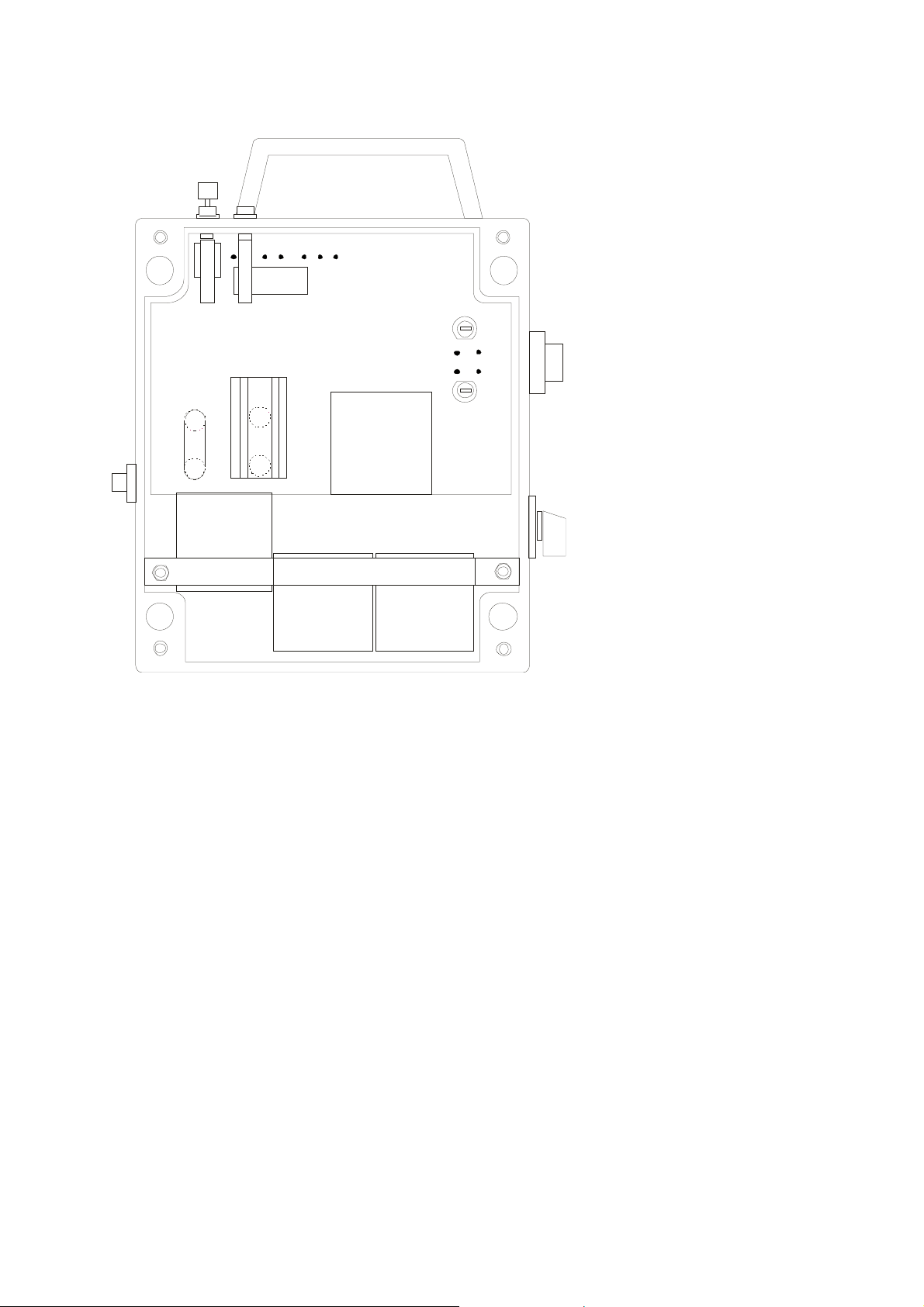
opened, the heat sink (E1) next to the H -capacitor (C1) will become visible. It connects the two
spark gaps (see Fig. 3).
Loosen the two M 3 nuts with a 5.5-mm socket wrench, pull off the toothed lock washers and
remove the heat sink. Turn out both spark gaps. Please take care when fitting in the new spark
gaps that they are screwed in finger-tight (i.e. without using any tools). The heat sink can be re-
assembled and fixed with the M 3 nuts and tooth lock washers. Reinsert fuse F 1 and close the
cover lid.
d.s.f. GmbH BZ – 24 TK ersion 11/2021 Page
9 of 10
Fig. 3
1
2
3
4
8
C1
E1
F1
F2
G1
G2
H 1
H 2
K1
S 1
S 2
32
33
X1
X2
charging voltage +
charging voltage -
protective conductor PE
LED connection, tin-coated
LED anode connection
capacitor
heat sink
fast 2,5 A fuse
fast 3,15 A fuse
gel lead battery
gel lead battery
indicator light (yellow LED)
discharge voltage (red LED)
relay
switch (on/off)
push-button ON
spark gap
spark gap
charger connection
high-voltage connection
K 1
7 810 9
T 2
C 1
X2
3 2
33
E 1
1
2
3
F 1
F 2
X1
6
5
G 1G 2
H 1
S 2
S 1
H 2
7. Maintenance
Because of its heavy-duty design, the igniter does not require any maintenance. Should deposits
settle on the spark plug due to the plant’s specific conditions, they can be removed with a cloth or
a brush (but do not use metal brus es, in order to avoid s ort circuits). When doing so beware
of the spark plug temperatures.
8. Spares
The high-energy spark plug and the spark gaps are wear parts and will not come under the war-
ranty conditions. The useful life of these parts depends on the number of ignitions and the ambient
conditions.
8.1. Spare part list
High-energy spark plug: Type HK 20/40 Part No. Z 100.3
Spark gap: Type 800 Part No. Z 106
Ignition lance with H -cable: Type ZS 100 K Part No. Z 122.1 (for example 1000 mm)

d.s.f. GmbH BZ – 24 TK ersion 11/2021 Page
10 of 10
9. Delivery conditions
Deliveries will basically be made on the basis of our General Terms and Conditions.
10. Storage
To maintain the full power supply of the lead-gel-battery in the ignition device, the products should
not be stored for more than 24 months without a new charge. It is recommended to maintenance
charge the battery every 6 months using the charger supplied. (See chapter 4)
Please note:
The spark gap and the high-energy spark plug are wear parts and thus exempted from the
warranty, since their service life depends on the number of ignitions and the conditions of use.
11. Warranty
From the day of delivery, we accept the warranty for a period of 24 months to eliminate possibly
errors or defects may cause an exchange. Requirement is, that an error can be attributed to defects
in components or manufacture.
The warranty is void if procedures are performed by the user or by third parties that is not expressly
authorized in writing by us.
Repairs will be done exclusively in our own repair shop. We do not accept repair bills from others.
The delivery of faulty equipment at d.s.f. GmbH must be freight free.
12. Liability
We are not liable for consequential damages of any nature, which may arise in combination with
any of our products. For any claims resulting from the failure to comply with this instruction manual,
d.s.f. GmbH will also not be liable in any way.
Subject to changes and modifications in the sense of the technical progress without prior
notice.
d.s.f. GmbH
Spessartstraße 11
D-63263 Neu-Isenburg
Telephone +49 (0) 6102 / 7890-0
Telefax +49 (0) 6102 / 7890-40
E-mail: info@dsf-gmbh.de
www.dsf-gmbh.de
Inhaltsverzeichnis


