Daktronics DBH-150 Handbuch

DBH-150
BANNER HOIST OPERATIONS & MAINTENANCE MANUAL


Daktronics Automated Rigging System
Manufacturer’s contact info
7200 Rawson Road
Victor, New York 14564 USA
tel 866-486-7835 585-924-5000
fax 585-924-0545
Daktronics Australia Pty Ltd
Unit 216, 354 Eastern Valley Way
Chatswood, NSW 2067,
ABN 53 131 659 455
tel +61 (2) 9417 3812
fax +61 (2) 9417 3868
web site www.daktronics.com/rigging
DBH-150 Banner Hoist
Operations & Maintenance Manual
Rev 0 DD1979034 3 June 2011
BANNER HOIST OPERATIONS & MAINTENANCE MANUAL

TABLE OF CONTENTS
01 SAFETY INFORMATION 1
02 GENERAL INFORMATION 3
03 GENERAL OPERATION/CONFIGURATION 5
Banner Hoist Remote
Powering On/Off 5
Raising/Lowering 5
Battery Maintenance 5
RF Tuning/Maintenance 6
04 MAINTENANCE/INSPECTION 7
Adjust & Inspect Banner Hoist
DBH-150 Limit Switch Operation & Adjustment 7
Initial Lower Limit Adjustment 8
Initial Upper Limit Adjustment 8
Mechanical Inspection 9
Electrical Inspection 10
Visual Inspection 10
05 WARRANTY INFORMATION 11
i

Warnings, Cautions, and Notes
All Warning notes contained in this manual indicate information that may endanger personnel.
WARNING
Before working on any of the Daktronics hoists, the main electrical disconnect must be
turned off and locked out according to U.S.A. OSHA regulations 29 CFR 1910.147 or
Australian regulations AS 1418.1 Section 8.10.3.4.
The Daktronics rigging system is designed to raise and lower equipment under the rated hoist capacity ONLY.
Only trained and authorized personnel should be permitted to operate the Daktronics system. The unauthorized use,
alteration, or use for purposes other than those for which it was designed may cause injury to persons, damage to
the equipment, or create conditions which could lead to fatalities. All proper safety considerations must be observed.
While operating the Daktronics rigging system, a spotter must be used in conjunction with the user at all times. The
spotter must have a clear view of all moving elements while maintaining contact with the user. If an unsafe situation occurs, the
spotter must immediately signal the user to halt all movements until the environment is cleared of any person or obstruction.
All installation and maintenance involving the Daktronics drive unit itself or the main electrical control cabinets
will require trained personnel. Simple daily maintenance activities of the workstation may be carried out by the
operators, and in most cases will be all that is needed once installed.
Electrical Safety—General Warning
WARNING The voltages used in the motor drive and master control panels can cause severe electrical
shock and/or burns. Extreme care is necessary at all times when working with the motor
drives. Only authorized personnel should carry out any installation, commissioning, or
maintenance of the electrical systems. All drive systems have been tuned at the factory
and will not require any additional alteration or adjustment by the owner’s personnel
unless specifically authorized by a Daktronics representative.
01 SAFETY INFORMATION
1
SAFETY INFORMATION

2

WARNING The Daktronics Banner Hoists are not designed to raise and lower people.
These hoists should NEVER be used for this purpose.
The DBH-150 unit must only be used with a maximum load equal to the capacity stated for the
model below. Overloading the system may result in serious injury or an inoperable system
The Daktronics hoist system is an automated rigging system, meaning that the load is not counter-weighted. Each
hoist can lift loads only up to the design capacity. Overloading will result in electrical overload protection shut
down of the hoist and possible damage to rigging components.
WARNING If it is necessary to operate a hoist from a location where the operator's view of the moving
load is obstructed, a second person must be used to observe the load and communicate to
the operator.
Dimensions of DBH-150 Unit
• Averageweightofself-containedhoistmoduleis88lb(39.9kg).
• Height=11.9"(303mm)
• Length=55.1"(1400mm)
•Width=9.9"(251.5mm)
DBH-150 Unit Overview
The Daktronics Banner Hoist is a chain-driven self-contained hoist platform that can be powered using single phase
120V 60Hz or 240V 50Hz electricity. The electricity powers the chain motor which rotates the drums, as well as the
power supply that in turn powers the RF receiver built into the hoist with 24 V DC power. It also controls the operation
of the chain motor and brakes.
The load is raised and lowered by the two available lift lines, utilizing “Zero-Fleet Angle” design architecture to ensure
that the cabling does not wind up on top of itself, protecting the cable and drum from wear.
Control over the unit is performed by utilizing the hand-held RF remote within line of sight of the hoist. It allows the
user to power on/off the unit, raise/lower the lift lines, and remotely program the RF remote to correspond to multiple
receivers, allowing one to control multiple banner hoists at once with one remote simultaneously. The RF remote
requres 2 AA alkaline batteries in order to operate.
02GENERAL INFORMATION
GENERAL INFORMATION 3

4
03 GENERAL OPERATION/CONFIGURATION
RF Controller
Limit Switch Nylon Drum
Motor Mounting ClipCable GuideElectrical Panel
Drum Chain Drive
Secondary Electric Brake
Drum Cable Keeper
Electrical Panel
Cable Guide Chain Drive
Specifications of DBH-150 Unit
Speed 0-20 ft/min (0.1 m/s)
Gross Lift Capacity 150 lb (68.03 kg)
Maximum Travel Standard travel 60' (18.2 m)
Number of Lift Lines 2 available
Electrical/HP Single Phase, 120V or 240V - 60 or 50HZ
Braking Primary & Secondary brakes are electromechanical type, rated at a minimum 150%
of full load (225 lb / 120.05 kg)
Control Wireless hand-held remote control
Mounting Standard units to be underhung horizontally.
Discuss special mounting requirements with Daktronics.
Cable&Drum 3/32"SteelWireRope
Covers Lightweight aluminum covers are standard for all units
Product dimensions: Length: 55.1"(1400 mm)
Height: 11.9"(303 mm)
Width: 9.9"(251.5 mm)
Crated dimensions: Length: 67"(1702 mm)
Height: 22"(559 mm)
Width: 18"(457 mm)
Weight: 88 lb (39.9 kg)
Component Diagram

BANNER HOIST REMOTE
The Banner Hoist System operates using a wireless remote
control that communicates with the hoist using radio wave
RF transmission. When operating the Banner Hoist system,
always have a clear line of sight to the hoist to minimize RF
interference and to promote safe operational use.
Powering On/Off
To power up the Banner Hoist, simply press the green
START button (Figure 1). To power it down, press the
red STOP button.
Raising/Lowering
To raise the Banner Hoist, simply press the UP button
and press the DOWN button.
Battery Maintenance
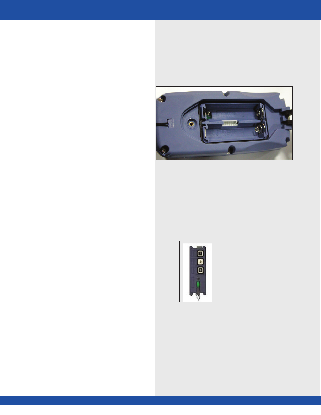
To replace the two AA alkaline batteries remove the
screw on the plastic back plate using a flat-head screw
driver (Figure 2).
Replace the batteries and screw the back plate into
proper position.
Figure 2: Banner Hoist Remote back
03 GENERAL OPERATION/CONFIGURATION
5
Figure 1: Banner Hoist Remote front
GENERAL OPERATION/CONFIGURATION

6
RF Tuning/Maintenance
There are two ways to tune the remote and the hoist
assembly so that they synchronize. The first method is
through reprogramming the remote using the remote
interface plug (Figure 3) in conjunction with the
Copy Module #700PROC pendant (Figure 4) next
to the batteries. The second and less time consuming
method is through using the remote itself next to the
antenna receiver to program the receiver to respond
to the remote’s transmitting signal.
A. To program the receiver to respond to a
specific remote, first ensure the remote and
receiver are of the same model, and
operate on the same frequency band by
opening up the remote and receiver and
ensuring their frequency crystals match.
B. Place the remote as close as possible to the
receiver to avoid unnecessary interference.
C. Turn off the receiver’s power supply, then turn
it back on. Because the receiver is fed power
through the hoist itself, turn the hoist
assembly on and off.
D. Within 4 minutes of turning the Daktronics
Banner Hoist back on, press and hold the
STOP button. Continue holding and then press
and hold the DOWN button. While holding
the previous two buttons press the UP button
4 times, and release all the buttons when the
red LED light on the remote flashes. If done
correctly the remote and receiver on the hoist
should be synchronized.
E. It is possible to program multiple hoist receivers
to respond to one remote I.D. through this
programming method.
F. If the remote programming data has become
corrupt or access to the hoist receiver for
optimal remote synchronization is restricted, use
of the Copy Module #700PROC can allows
copying the programming data of one remote
into another remote, allowing that remote to
work with the equipment the source remote
is programmed to work with. (Copy Module
#700PROC sold optionally.)
G. If problems continue with the remote and/or the
receiver on the hoist, consult with Daktronics,
see manufacturing contact on the inside cover
of this manual.
Figure 3: Banner Hoist Remote Interface Plug
Figure 4: Copy Module #700PROC

Inhaltsverzeichnis
Beliebte Kettenzug Handbücher anderer Marken

EINHELL
EINHELL Herkules H-F 1000 Bedienungsanleitung

RED ROOSTER
RED ROOSTER TCR-250 Bedienungsanleitung

POWERTEX
POWERTEX PCB-S1 Bedienungsanleitung

Parkside
Parkside PSZ 250 A1 Bedienungsanleitung

Ingersoll-Rand
Ingersoll-Rand QCH Series Bedienungsanleitung

Creative Conners
Creative Conners CM Varistar Smart Chain Hoist Bedienungsanleitung