ddtop UHC Magnetic Level Gauge Bedienungsanleitung

1/ 17
WWW.DDTOP.COM
UHC | Bb-Remote Transmission
MAGNETIC LEVEL GAUGE
Operating Manual
UHC-Bb-DT-JS-1027-2018(A)

2/ 17
WWW.DDTOP.COM
PREFACE
Thank you for choosing the products of Dandong Top Electronics Instrument (Group)-Co.,Ltd.
This operation manual provides you with important information on installation, connection and
commissioning as well as on maintenance, troubleshooting and storage.
Please read it carefully before installation and commissioning and keep it as part of the product
near the meter for easy reading.
This manual can be downloaded by entering the version number at www.ddtop.com.
If the instructions are not followed, the protection provided by the meter may be destroyed.
Trademark, Copyright and Restriction Instructions
Dandong Top Electronics Instrument (Group) Co.,Ltd.®, Dandong Top Pump Co.,Ltd.®,
DDTOP® are registered trademarks of the company.
The performance specifications of the meter are effective as of the date of publication and are
subject to change without notice. Dandong Top Electronics Instrument (Group)Co.,Ltd. reserves the
right to modify the products described in this manual at any time without prior notice.
Quality Assurance
Dandong Top Electronics Instrument (Group) Co.,Ltd. guarantees that all variable area flow meters
have no defects in materials and manufacturing processes within one year from the date of delivery.
During the warranty period, if the product returns with quality problems and the claim is
determined by the manufacturer to be within the scope of warranty, Dandong Top Electronics
Instrument (Group) Co.,Ltd. is responsible for repair or replacement of the buyer (or owner) free of
charge. Dandong Top Electronics Instrument (Group) Co.,Ltd. is not responsible for the costs caused
by improper use of equipment, labor claims, direct or subsequent damage and installation and use
of equipment. In addition to the special written warranty certificate for certain products of Dandong
Top Electronics Instrument (Group) Co.,Ltd., Dandong Top Electronics

3/ 17
WWW.DDTOP.COM
Instrument (Group) Co.,Ltd. does not provide any express or implied warranty.
Quality
Dandong Top Electronics Instrument (Group) Co.,Ltd. has passed the ISO9001 quality system
certification. The whole process of product production is strictly in accordance with the scope of
the quality system, providing the strongest guarantee for product and service quality.

4/ 17
WWW.DDTOP.COM
Contents
1. Safety Tips..................................................................................................................................................................5
2. Product Descriptions ..............................................................................................................................................5
3. Technical Parameters .............................................................................................................................................6
4. Outline Dimension Diagram ................................................................................................................................7
5. Unpacking and Inspection....................................................................................................................................8
6. Installation..................................................................................................................................................................8
7. Configuration ......................................................................................................................................................... 10
8. Precautions ............................................................................................................................................................. 15
9. Fault Analysis and Troubleshooting ............................................................................................................... 16
10. Disassemble........................................................................................................................................................ 16
11. Product Certification........................................................................................................................................ 16

5/ 17
WWW.DDTOP.COM
1. Safety Tips
For safety reasons, it is expressly prohibited to modify or change the product without authorization.
Repair or replacement is only allowed to use the accessories specified by the manufacturer.
1.1 The explosion may cause death or serious injury.
When installing the device in an explosive environment, be sure to comply with applicable local,
national and international standards, codes and regulations. Ensure that the equipment is installed
in accordance with intrinsically safe or non-flammable site operating procedures.
1.2 Process leakage may cause serious injury or death.
If the process seal is damaged, the medium may leak at the connection.
1.3 Failure to follow the safety installation guidelines may result in death or serious injury.
All operations described in this manual must be carried out by trained and qualified or
end-user-appointed personnel.
2. Product Descriptions
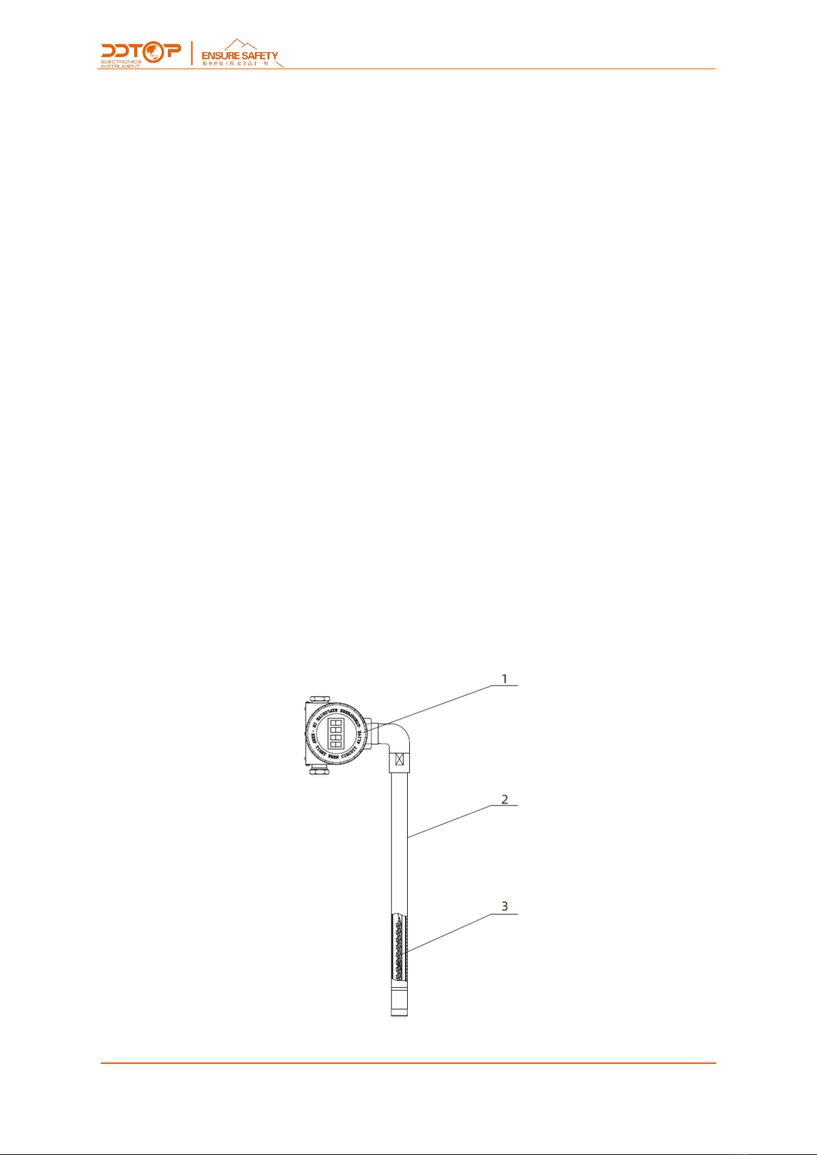
2.1 Main Structure Figure 1-Remote Transmission
Figure 1 Product Constructure

6/ 17
WWW.DDTOP.COM
1. Meter head assembly, converter circuit and LCD screen
2. Housing, protect the sensor circuit
3. Reed switch-resistance component, sensor circuit
2.2 Working Principle
The magnetic float in the measuring tube moves up and down with the fluid level or interface level
of the medium, so that the resistance value in the sensor circuit changes linearly, and then the
resistance value change is converted into a 4-20mA standard DC signal through the converter
circuit in the meter head assembly. LCD display or output to the control room through the output
terminal to achieve long-distance transmission of liquid level.
2.3 Packaging
Please take the packaging waste to a special recycling facility。
2.4 Lifting and Transportation
Please use quality lifting equipment and lifting straps, and pay attention to safety.
2.5 Storage
Storage temperature -20℃~40℃
Storage humidity≤40%
3. Technical Parameters
3.1 Key Performance
3.1.1The remote transmission device has passed the national explosion-proof certification
Certification mark:Intrinsically safe Ex ia ⅡC T1~T5/T6 Ga;
Flameproof Ex d ⅡC T1~T5/T6 Gb
3.1.2 Executive standard
GB/T 25153-2010 Magnetic level gauge for chemical pressure vessel
JB/T 12957-2016 Magnetic level gauge

7/ 17
WWW.DDTOP.COM
3.2 Main Parameters
Measuring Range
0~6000mm(>6000mm special customized)
Power Supply
24V DC
Output
4~20mA DC(with HART)
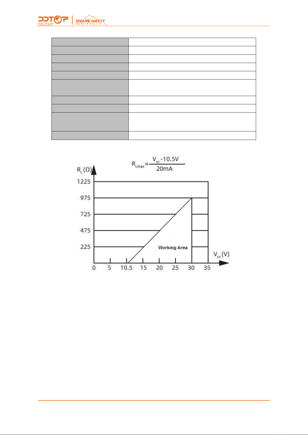
Load Characteristics
See load characteristics chart (Figure 2)
Ambient Temperature
-40℃~+80℃
Working Temperature
-40℃~+200℃(When T≥150℃, the transmitter does not
allow heat preservation)
Accuracy
±5mm
Power Inlet
M20×1.5(female thread) or as customer requirement
Explosion-proof Type
Intrinsically safe Ex ia ⅡC T1~T5/T6 Ga
Flameproof Ex d ⅡC T1~T5/T6 Gb
Ingress Protection
IP66
Figure 2 Load Characteristic Diagram
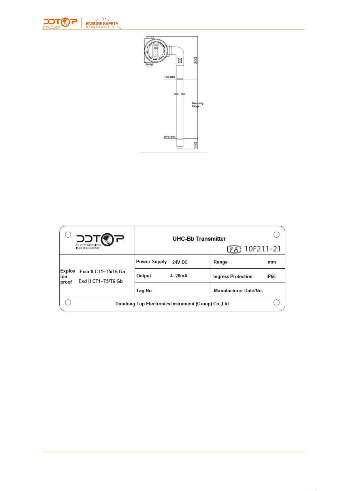
4. Outline Dimension Diagram
If special size is required when ordering, the actual size shall prevail.

8/ 17
WWW.DDTOP.COM
Figure 3 Remote Transmission Device
5. Unpacking and Inspection
5.1 Precautions for unpacking inspection
5.1.1 Check whether the product nameplate is consistent with the packing list information Figure 4
Figure 4 Product Nameplate
5.1.2 Check the quantity and material of each part against the packing list.
5.2 Content of Inspection
Check the appearance of the instrument for defects, damage and other abnormalities
6. Installation
6.1 Installation Tools
Hose clamp, screwdriver

9/ 17
WWW.DDTOP.COM
6.2 Installation and operation process - Figure 5
Figure 5 Installation
6.2.1 When installing the remote transmission device, as shown in Figure 5, the zero point full scale
of the remote transmission device (marked at the factory) and the O scale full scale of the on-site
indicator on the measuring tube are one-to-one correspondence, and then fixed with a hose
clamp.
6.2.2 Remote transmission device wiring: after removing the cover, you can connect according to
the wiring diagram in Figure 6
Figure 6 Transmitter Wiring Diagram

10 / 17
WWW.DDTOP.COM
7. Configuration
7.1 Transmitter Configuration
This section mainly introduces how to use the 3 local keys (Enter key←┘), (up key "↑"), (down key
"↓"), combined with LCD display to configure internal parameters.
7.1.1 LCD display function overview
See (Figure 7-1) for full screen information. The variables that can be displayed on the LCD screen
include current (Figure 7-2), percentage (Figure 7-3) and main variable (Figure 7-4). You can set to
display a single variable, or you can set the percentage and the main variable to cycle display, and
the effective digits of the decimal part can be set (0, 1, 2, 3, 4 decimal places). The display mode is
set by 475 configuration software or button. If the percentage and main variable are set to be
displayed cyclically, the LCD will display these two variables alternately with a period of 3 seconds.
Figure 7-1 Full LCD display Figure 7-2 Current display
Figure 7-3 Percentage display Figure 7-4 Main variable display
7.1.2 LCD Display Symbol Description
①If it is in HART communication status, the symbol on the right corner of the LCD
screen will flash.
Inhaltsverzeichnis
Andere ddtop Mikrofonsystem Handbücher
Beliebte Mikrofonsystem Handbücher anderer Marken

Sennheiser
Sennheiser Evolution Wireless Digital EW-DX EM 2 Bedienungsanleitung

Alpha Technologies
Alpha Technologies RBMS Bedienungsanleitung

SWIT Electronics Co.,LTD.
SWIT Electronics Co.,LTD. CW-S150 Bedienungsanleitung

Shure
Shure UA844 Bedienungsanleitung

Panasonic
Panasonic SHFX70 - DVD HOME THEATER WIRELESS SYSTEM Bedienungsanleitung

Pyle
Pyle PDWM5000 Bedienungsanleitung