
Delta-T Devices SunScan SS1-RL4 Bedienungsanleitung

User Manual Supplement for the
SunScan System
Radio Link
type SS1-RL4
SS1RL-UM-2.0
Delta-T Devices Ltd

Notices
Copyright
All rights reserved. Under the copyright laws, this manual may not be
copied, in whole or in part, without the written consent of Delta-T Devices
Ltd. Under the law, copying includes translation into another language.
Copyright © 2006,2008 Delta-T Devices Limited
BF2 and BF3 Sunshine Sensor optics design and theory are Copyright ©
1996 John Wood, Peak Design & Development, Winster, Derbyshire, U.K.
and protected by Patent Nos: 1012633 (EU), 6417500 (US).
Trademarks
Windows is a registered trademark of Microsoft Corporation.
All other trademarks are acknowledged. Some names referred to are
registered trademarks.
CE Conformity
For a copy of EMC compliance certificates
contact Delta-T at www.delta-t.co.uk
Warnings
To maintain conformance to CE standards, the equipment must be used
as described in this supplement and in the SunScan Canopy Analysis
System user manual. Modifications to the equipment may invalidate CE
certifications.
Delta-T Devices Ltd reserves the right to change the designs and
specifications of its products at any time without prior notice.
Authors
John Wood, Edmund Potter, Nick Webb.
User Manual Version: 2.0 May 2008
Delta-T Devices Ltd Tel: +44 (0)1638 742922
130 Low Road, Burwell Fax: +44 (0)1638 743155
U.K. web: http://www.delta-t.co.uk

Contents
Introduction 5
The SunScan System Radio Link 5
Achievable Range 6
About this Manual 6
Other Documents Required 6
Upgrade Systems 6
Unpacking 7
Components 7
Health and Safety Issues 8
Description 8
SunScan Probe 8
Transmitter Module 9
Getting Started 10
Familiarisation 10
Preliminary Checks 10
Transmitter Module and BF3 10
SunScan Probe 11
Testing the Range 11
Field Techniques 12
Measurement Procedures 12
Initial Considerations 12
Locating the BF3 Sensor 12
Field Calibration Check 12
Optimising the Range 13
Trees and Tall Canopies 13
Technical Reference 15
Specifications 15
Radio Link Performance 15
Range Disclaimer 15
SunScan Transmitter Module type BF-RL4 15
SunScan Radio Probe type SS1-RL4 15
Tripod Mounting Plate for BF3 and BF-RL4 16
Routine Maintenance 16
Batteries 16
Desiccant 17
SunScan Radio Link Supplement v2.0 Contents z3

Warranty and Service 18
Terms and Conditions of Sale 18
Service and Spares 19
Technical Support 19
Contact Details: 19
Troubleshooting 20
Procedure 20
BF3 Check 20
BF-RL4 Transmitter Check 21
SS1-RL4 Probe Check 21
Problem Reporting 22
Appendix A: Technical Design Information 23
CE Certification 23
Radio Certification (EU) 23
Radio Link 23
Routine Servicing 23
Component Diagram 23
Radio Protocols 24
Diagnostic Information 25
Index 26
4 zContents SunScan Radio Link Supplement v2.0

Introduction
The SunScan System Radio Link
The SunScan radio link is designed to give cable-free operation of the
SunScan system in field use. It is no longer necessary to connect the
SunScan probe to the reference Sunshine Sensor BF3 by a sometimes
substantial length of cable (the BFXL cable).
The radio link can be used in low canopies (field crops, cereals, etc) and
in tree canopies (orchards, tree nurseries, etc).
Handling and manipulating the BFXL cable within a crop has often been a
laborious aspect of SunScan measurements. In addition, the BF3 sensor
had to be relocated frequently. The advantages of the radio system are
considerable:
♦BFXL cable handling and wear is avoided
♦Sampling measurements can be taken much faster
♦Distances over 100m from the BF3 sensor are possible
♦Fewer BF3 relocations give quicker operation.
SunScan Radio Link Supplement v2.0 Contents z5

Achievable Range
The radio link works on a licence-free frequency in EU countries. The
transmitter power is regulated by law, and this limits the clear line of sight
range in good conditions to a maximum of about 250m.
The maximum achievable range in real field conditions, working within
canopies, will be less than this. It will depend on the nature of the foliage
in the canopy, and whether it is wet or not. In addition there may be local
sources of electromagnetic RF interference that could reduce the
achievable range.
Disclaimer! In practical use we do not guarantee any minimum range, or
that the radio link can be used at all, in a particular situation. The radio link
is an option. If it cannot be used, the alternative is to use the BFXL cable,
which remains an essential part of a full SunScan system.
About this Manual
This manual describes only the radio link components for use with the
SunScan Canopy analysis System, and it concentrates on the different
procedures needed when the radio link is used instead of the normal
BFXL cable connection.
The radio link is supplied as part of a full SunScan Radio System. The
system must include a Sunshine Sensor type BF3 (or the earlier BF2
model).
The main components of the radio link are the transmitter module type
BF-RL4, and the SunScan probe with built-in radio receiver type SS1-RL4.
Other Documents Required
The operation of the SunScan system, without using the radio link, is fully
covered in the SunScan Canopy Analysis System User Manual. This will
be referred to as the SunScan manual.
You will also need the User Manual for the Sunshine Sensor BF3 This will
be referred to as the BF3 manual.
Upgrade Systems
Existing systems with BF3 or BF2 sensors can be returned to Delta-T for
conversion to the radio link. The radio link cannot be used with the original
BF1 Beam Fraction sensor.
If you have a BF2 sensor, please interpret references to the BF3 in this
document as applying to the BF2. There are some differences but these
should be obvious to the BF2 user.
6 zContents SunScan Radio Link Supplement v2.0
Unpacking
When unpacking the components for the first time, check that you have
received the following items specific to the radio link.
Warning! If anything is damaged or missing, you must immediately notify
the carriers. You may be unable to claim, if you delay. Also notify your
distributor or Delta-T, with details of damage or missing items.
Components
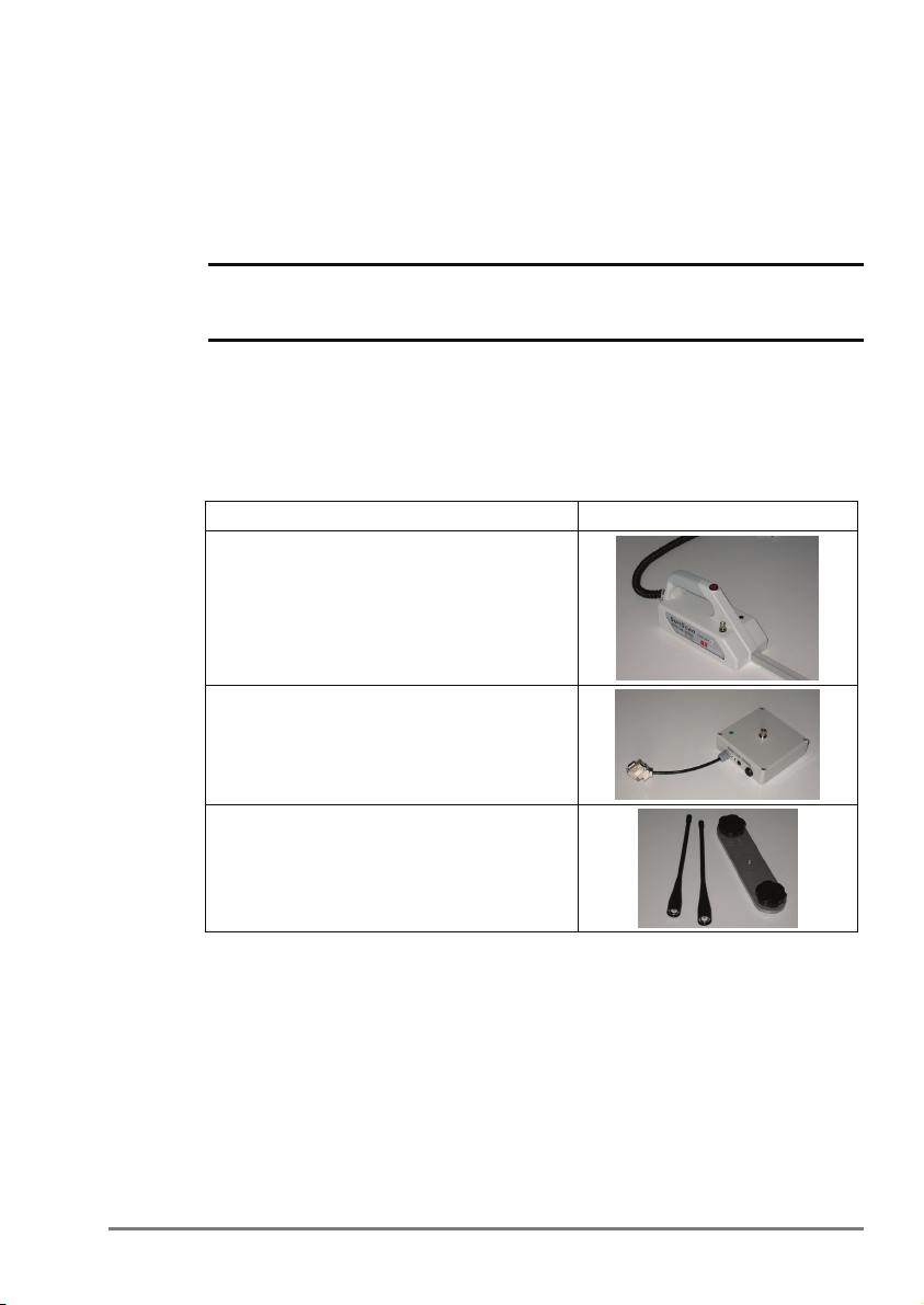
The SunScan Radio Link system comprises of a SunScan Probe SS1-
RL4, the Transmitter module BF-RL4, and a pack containing the mounting
plate and two removable antennas as illustrated below. This radio link
user manual supplement is included.
Sales Code and description:
SunScan Probe type SS1-RL4.
The radio version is distinguished by the
antenna connector and probe LED built
into the handle.
Radio Module (transmitter) type BF-RL4
Mounting plate and two identical antennas.
The mounting plate fits on to the tripod for
the BF3.
SunScan Radio Link Supplement v2.0 Contents z7

Health and Safety Issues
The Radio Link works on a 434 MHz frequency, licence-free in the EU,
and in some other countries world-wide. The transmitted power is
restricted to 10mW.
Note: There are no known health and safety issues associated with the
use of this frequency and power level.
There is no health hazard involved in touching the antennas while they are
in use, but you should not do this because it may contravene the certified
operating conditions.
There is no danger to the radio systems if they are operated without the
antennas in place or properly connected. However, you should avoid
doing this wherever possible.
Description
SunScan Probe
Probe LED
The radio link receiver circuit is built into the probe handle. When the radio
system is in use, the probe LED indicates whether or not signals from the
BF-RL4 radio transmitter are being picked up.
The radio receiver is powered from the same batteries that power the
SunScan probe.
The handle can be dismantled from underneath to access the batteries
and to replace a desiccant pack from time to time (see Routine
Maintenance section).
Antenna
connector
A
ntenna
8 zContents SunScan Radio Link Supplement v2.0

Transmitter Module
The radio module contains the radio link transmitter. It also contains
batteries.
♦The module case can be dismantled (four corner screws) to access
the batteries and to replace a desiccant pack from time to time (see
Routine Maintenance section).
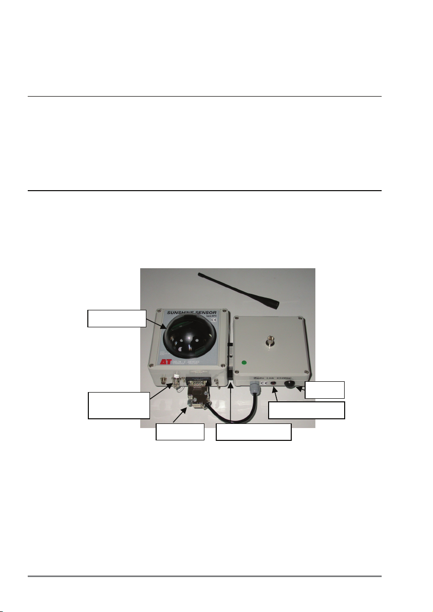
♦To switch on, depress the on/off button. The button remains in the
depressed position.
♦To switch off, press the button again. The button will return to its
outward position.
♦If the module is powered and switched on, the red LED will flash to
indicate it is working.
Transmitter LED
RS232 for BF
3
O
n
/o
ff
butto
n
Antenna
connector
SunScan Radio Link Supplement v2.0 Contents z9
Getting Started
Familiarisation
If you are new to the SunScan system, then work through the SunScan
manual to get the system going normally without using the radio link.
If you are already familiar with the functioning of the SunScan system it is
better to confirm normal operation with the BFXL cable first, then proceed
through the steps below.
Preliminary Checks
Transmitter Module and BF3
Fit the BF-RL4 transmitter module on to the mounting plate next to BF3,
and mount them both on to the tripod.
BF3 LED
♦Connect the transmitter cable to the BF3 RS232 connector. If you
were using the system without radio, disconnect the BFXL cable from
the BF3 and from the SunScan probe.
♦Connect the antenna. Make sure there is no chance of its shadow
falling on the BF3 dome when it is positioned in the field.
♦Depress the on/off button on the transmitter to start. You will see
the transmitter LED flash every 3 seconds.
BFXL cable
connector
Mountin
g
p
late
Transmitter LED
On/off
RS23
2
10 zContents SunScan Radio Link Supplement v2.0


