Dembla 7400 Series Bedienungsanleitung

Instruction Manual
D Butterfly Valve
Series 7400
ouble Offset
1Feb 2009
0062
2 G/D T 3/4/5/6

CONTENTS PAGE NO.
2
1.1 Introduction 2
1.2 Scope of Instruction Manual 2
1.3 Copyrights and Modification Rights Reservation 2
2
3
4
5
6
8
7.1 Pre-Installation Checks 8
7.2 Operation 8
7.3 Lubrication 8
9
9
9.1 V-PTFE Packing 10
9.2 Double V-PTFE Packing 10
9.3 Grafoil Packing 11
9.4 Double Grafoil Packing 11
9.5 V- Low Fugitive Emission Packing 12
9.6 Grafoil Low Fugitive Emission Packing 12
13
10.1 Replacing Guide Bush (Bearings) 14
10.2 Trouble Shooting 15
15
11.1 Operation 16
11.2 Removing Hand Lever Operator from the Valve Body 16
17
12.1 Operation 17
12.2 Setting of Gear Box Type Operator 18
19
13.1 Fixing / Mounting Hand Lever on Body Set 19
13.2 Fixing / Mounting Gear Box Type operator on Body Set 19
20
14.1 Butterfly Valve Assembly Flange: - Size 2” (50mm) to 6” (150mm) 20
14.2 Butterfly Valve Assembly Flange: - Size 8” (200mm) & 72” (1800mm) 21
22
22
1.0 Foreword
2.0 Storage & Preservation
3.0 Valve Marking
4.0 Health & Safety
5.0 Unpacking
6.0 Lifting Details
7.0 Installation of Butterfly Valve
8.0 Maintenance
9.0 Replacing Gland Packing
10.0 Replacing Soft Seat
11.0 Hand Lever Type Manual Operator
12.0 Gear Box Type Manual Operator
13.0 Installation of Manual Operator
14.0 Parts Illustrated
15.0 Torque for Studs
16.0 Recommended Spare Parts
PTFE
1

1.0 Foreword
1.1 Introduction
1.2 Scope of Instruction Manual
1.3 Copyrights and Modification Rights Reservation
2.0 Storage & Preservation
Dembla High Performance Butterfly Valves are available in Flange type Designs conforming to API 609
standard. The Disc construction is Double Offset. Shafts are guided by bearing. Various seat options are
available.
This Instruction Manual covers information regarding Installation and Maintenance of Dembla's Double
Offset High Performance Manual Butterfly Valves Flange type, Series 7400.
No person may Install, Operate or Maintain Dembla Valve without 1) being fully trained and qualified in
Valve, Actuator and Accessory Installation, Operation and Maintenance 2) Carefully reading and
understanding the contents of this manual. If you have any questions about these instructions contact
your Dembla Sales Office before proceeding.
Dembla Valves Ltd. retains the Copyright on the contents of this Instruction Manual.
The total content of this Instruction Manual described here corresponds to the information
during preparation of the Instruction Manual. It is user's responsibility to refer the latest version.
All data, specifications and illustrations here are subjected to Technical Modifications and
improvements and hence Modification can be done by us at any time without any prior notice.
No claim to Modification or repair of these Valves, which have already been supplied by us, can
be made.
All Valves are dispatched in the closed/open position as ordered and it is recommended that they are left
in this position during Storage. All protective Packing should remain in position until the Valve is to be
Installed. Valve should be stored in a clean and dry environment, without disturbing company setting.
(e.g. Gland, Seat etc.) Protect it from shock & lifting damage.
If hoisting the Valve, use a nylon sling to protect the surface. Carefully position the sling to prevent damage
to Actuator tubing and any Accessory. Also, take care to prevent people from being injured in case the hoist
or rigging slips unexpectedly. For Valve weight refer Valve Packing slip.
!Caution
2

3.0 Valve Marking
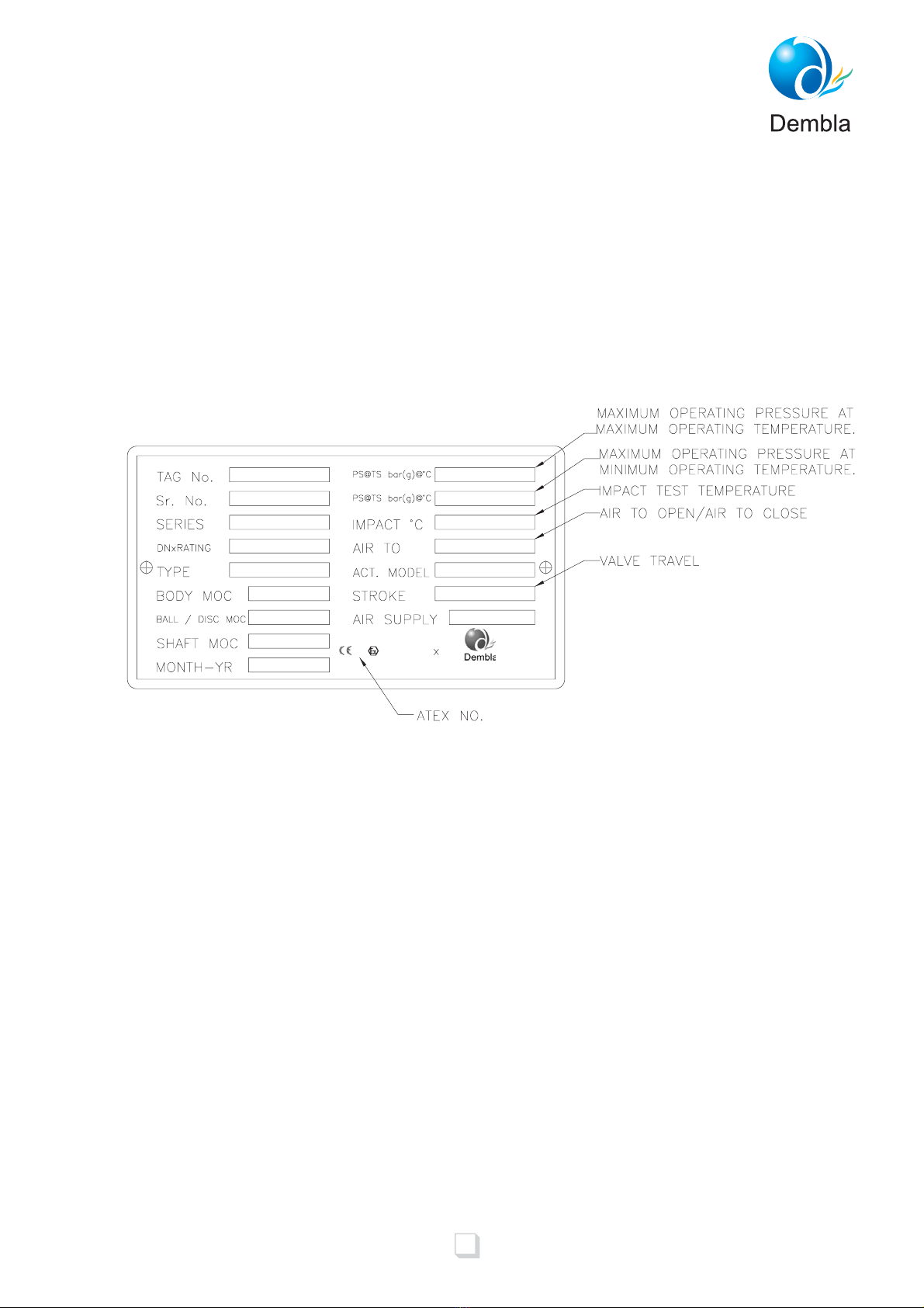
1) Valve name plate attached on Valve by riveting carrying all Valve Identification Information.
2) Markings like Valve Size, Rating, Material etc. are as cast on Valve Bodies.
3) Valve Serial No. punched on Valve Body Flange for Valve Traceability.
4) If the product is not CE marked, Then name plate is also without CE mark.
3
Name plate for
Series:-7400 Valves
0062
INDIA
II 2 G/D T *

4.0 Health & Safety
1) Before attending to Valve Installation / Maintenance, the Instruction Manual must be compulsorily read
and understood properly.
2) Valve must be operated by qualified personnel.
3) Ensure that the operator handling these Valves must follow Safety and Accident Prevention Rules and
Regulations.
4) Follow the Safety Instructions before Installation, Maintenance or removing the Valve.
5) Always wear protective gloves, clothing and eyewear when performing any Installation operations to avoid
personal injury.
6) All Safety Messages such as Cautions, Warnings and Notes are highlighted in this Instruction Manual
which must be strictly followed to avoid any possibility of arising danger / risk of damage to the
equipment / person's life
7) No Liability on Manufacturer for any wrong handling, improper commissioning and wrong assembly.
8) Line must be fully drained and de-pressurized before Installation or Maintenance of Valve.
9) Never handle Valves that have been used on harmful substances unless they have been completely
decontaminated and certified safe to handle.
10) Due to the large physical Size and weight of some Size of this product, always use correct lifting methods
and equipment when Installing , removing and maintaining the product:
Use lifting lugs on the body, wherever provided.
Valve without lifting lugs-use chains or slings wrapped around the body.
Do not attempt to lift the Valve using the Sealant Fittings, Gear Unit, Handwheel, Actuator, or the Valve
Stem.
11) If the processes or environments that the products are used in are likely to cause temperature (high or low)
that may cause injury to person if touched, then adequate Insulation / protection must be fitted.
It is recommended that the insulation allows easy access for Maintenance, to the Sealant Fittings, and to
the Valve operator.
12) Valve must be protected from earthquake loading, traffic & wind.
13) No Modification / Conversions are allowed without written authorization from Dembla Valves Ltd.
Rise in temperature on surface of Valve Body depend on working Media. End user must be
maintaining the surface temperature & it should not go beyond marking temperature on Valve
(Name Plate).
4
!Warning
!Warning

5.0 Unpacking
For Carton
For Wooden Box
·
·
·
·
·
·
·
·
·
·
·
Keep Carton in position (Carton up side should not be down ).
Cut plastic strip properly which is tied around Carton & remove it. (White in colour).
Cut cello tape properly which is stuck on Carton opening.
Open Carton properly.
Remove foam properly along with polythene wrapping.
Lift the Valve properly & keep on clean & dry place
Keep Wooden Box in Position ( upside of Wooden Box should not be down ).
Cut iron strip properly which is tied around Wooden Box & remove it.
Remove nail properly from top cover with proper equipment.
Loosen and remove Valve fixing nut (from inside of Box).
Lift the Valve properly as shown in figure 1
5

6.0 Lifting Details
Valve should be lifted by using chain or bearer cables as shown in figure 1. (Take care that
Valve should not damage while handing).
6
Fig .1

·
·
·
·
·
·
·
·
1) An occasional cleaning of Valve Stem will prevent dirt or grit being carried away into the Packing.
2) Vary air lines and fitting to the Actuator to ascertain actual Travel Scale Indication.
3) Check all air lines and fitting to the Valve Actuator & Accessories for air Leaks.
4) Ensure that the combined action of Controller, Positioner and Valve provide the desired Valve
Stem Movement. Also ensure the required fail safe position of Control Valve.
Always wear protective gloves, clothing, and eye ware when performing any Installation
operation to avoid personal injury.
Valve should be used by End-user with same pressure & temperature rating which was given in
Valve Marking (Name Plate) If there is any change please contact Dembla Sales Office.
Avoid personal injury or property damage caused by components dropping .With the Valve or
Actuator upside, components may drop during disassembly or assembly. Be careful not to
position yourself below the Valve in the path of falling parts.
Personal injury could result from Packing Leakage. Valve Packing was tightened prior to
shipment, but should there be any Gland Leakage after Installation, further tightening, just
enough to stop Gland Leak is required. Excessive tightening will disturb Valve Calibration.
Our Valves can not be used for Defence, Nuclear, Telecommunication, Marine, Railway and
Laboratory & Mines.
Our Valve is valid for atmospheres having pressure ranging for 0.8 bar to 1.1 bar and
temperatures ranging for -20ºC to +60ºC
Earthing facility must be provided by the end user before operating the Valve.
Equipment should not be used for dead end service
After the Valve has been Installed, make a final check of the following :-
·In case of Leak, presence of high temperature may be dangerous to the person s life.
Equipment to be used as per intended and not misused / improperly used to avoid dangerous
effects such as over load ,over heating ,stress corrosion cracking, etc.
·
7
!Warning
!Caution

7.0 Installation of Butterfly Valve
7.2 Operation
7.3 Lubrication
7.1 Pre-Installation Checks: (Before Installing any Butterfly Valve)
(1) Inspect it for any shipment damage and for foreign material that might have collected during Packing and
shipment.
(2) Blow out all pipelines to remove pipe scale-chips, welding-slag, and other foreign materials.
(3) Install the Valve using accepted piping practices.
(4) Install the Valve according to flow direction marked on the Valve.
(5) Use self centering Gasket.
(6) Install the Control Valve preferably in a straight run of pipe away from bends or sections of abnormal
velocity.
(7) Incorrect pipe alignment will cause interference between the disc edge and line Flange face, excessive
torque and damage to disc and seat, resulting into Seat Leakage.
(8) Do not try to Install Valve between line flanges having inadequate gap. This may cause damage to some
Valve parts. If Valve is in fully open position, it will impact the Flanges and damage the disc edge.
(9) No butterfly Valve should be attempted to Install when disc in open condition. The butterfly Valve can be
inserted between line flanges in fully close position.
(10) Glands are factory tightened and checked for Leakage however if there is any Gland Leak in Valves, the
Gland may be further tightened just enough to stop Leakage. Excessive tightening should be avoided
(11) Connect the Valve in pipe line with the standard connections.
Valve closes with clockwise rotation of the Valve Shaft. Valve is fully closed when disc is parallel to Seat
Ring.
The Valve Body set does not require any routine lubrication. However Valve operator may require
lubrication which is to be referred in the Part-II Manual Operator Section of this Instruction Manual.
8

8.0 Maintenance
·
·
·
·
·
·
ning so that
the Body to bonnet joint will with stand test pressures and application service condition, before tightening
nuts make sure that Plug & Stem assembly is properly aligned with Seat Ring.
11) For the Installation of Gland Packing refer following 9.1 to 9.6
12) Mount the Actuator & Connect Stem Connector as specified in the “Reassembly of Actuator on Valve
Body” Refer Section 11.0 of this Manual.
Avoid personal injury or damage to process system from sudden release of pressure of
process fluid.
Before starting dis-assembly Use by-pass Valve or completely shut off the process to isolate
the Valve from process pressure. Drain fluid from both ends of the Valve.
Disconnect all operating lines providing air pressure, electric power or a control signal to the
actuator.
Any Gasket once removed should be replaced by a new one upon re-assembly. This is
necessary to ensure a good seal since the used Gasket may not seal properly.
Earthing facility and Valve parts (Bush) should be checked periodically by the end user.
Equipment should be cleaned regularly.
9.0 Replacing Gland Packing
1) Isolate the Control Valve from line pressure & release the pressure.
2) Remove Actuator from Valve Body as shown in section 8.1 “Removing Actuator from the Valve Body.
3) Remove the Nuts from Body Studs on Bonnet and lift the Bonnet carefully off the Body. If the Valve Plug &
Stem assembly starts to lift along with Bonnet, use a brass or Nylon hammer on the end of the stem & tap it
back down.
4) Remove the Valve Plug & Stem assembly from the Body.
Handle the Plug & Stem carefully to avoid the damage at seating surface of & Stem diameter.
5) Unscrew and remove Gland Flange Nut.
6) Remove Gland Flange.
7) Push out Gland Packing from the Bonnets bottom side Gland Packing& Spreader carefully take out by
using a rounded rod or other tool that will not scratch but clean the stuffing box wall.
8) Install Plug & Stem assembly. Then slide the Bonnet over the stem and on to the Body Studs.
9) Install new Packing Seal & Metal Gland Parts according to the appropriate arrangement.
10) Lubricate the Body Studs and Install the nuts. Use accepted bolting procedure during tighte
Set the Bonnet on a protective surface to prevent damage to the Bonnet Gasket surface.
9
!
Caution
Inhaltsverzeichnis
Andere Dembla Steuereinheit Handbücher
Beliebte Steuereinheit Handbücher anderer Marken

Festo
Festo Compact Performance CP-FB6-E Stücklistenhandbuch

Elo TouchSystems
Elo TouchSystems DMS-SA19P-EXTME Bedienungsanleitung

JS Automation
JS Automation MPC3034A Bedienungsanleitung

JAUDT
JAUDT SW GII 6406 Series Kurzanleitung

Spektrum
Spektrum Air Module System Bedienungsanleitung

BOC Edwards
BOC Edwards Q Series Bedienungsanleitung