Displax PAD Bedienungsanleitung

TECHNOLOGY FOR THE MULTITOUCH GENERATION
DISPLAX PAD
USER GUIDE

MKT.246.1 | DISPLAXTM PAD USER GUIDE 2
PACKING LIST........................................................................................................................3
GENERAL INFORMATION.................................................................................................4
HANDLING INSTRUCTIONS ...................................................................................................................4
TOOLS REQUIRED.....................................................................................................................................4
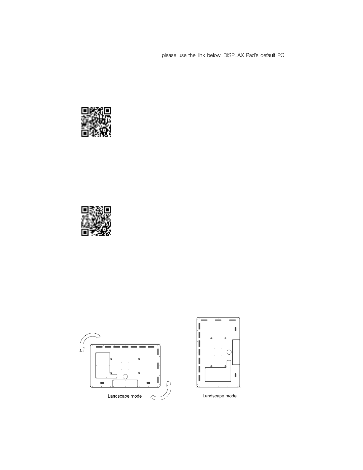
DOWNLOAD USER GUIDE AND DRIVERS.......................................................................................4
OTHER INFORMATION.............................................................................................................................5
PRODUCT DESCRIPTION.................................................................................................6
DISASSEMBLING & ASSEMBLING................................................................................9
HOW TO OPEN PAD..................................................................................................................................9
HOW TO REMOVE OR ASSEMBLE PC..............................................................................................9
HOW TO ACCESS THE PCB..................................................................................................................9
HOW TO REMOVE OR CHANGE LCD..............................................................................................11
SETTING UP DISPLAX PAD...........................................................................................12
SKIN MULTITOUCH CONFIGURATION....................................................................13
CARE & HANDLING..........................................................................................................14
SUPPORT..............................................................................................................................15
WARRANTY..........................................................................................................................16

MKT.246.1 | DISPLAXTM PAD USER GUIDE 3
PACKING LIST
This DISPLAX Pad shipment contains the following equipments/components:
Pad 1 unit
Remote control 1 unit
3D glasses* - 1 unit
* When technology available in LCD shipped
01

MKT.246.1 | DISPLAXTM PAD USER GUIDE 4
GENERAL INFORMATION
HANDLING INSTRUCTIONS
Due to the product weight, carrying and assembling DISPLAX Pad should be made by 2
persons.
Never place DISPLAX Pad with the glass facing down. Always make sure the unit is placed in
a surface clean and free of debris to avoid scratching or damaging.
Always make sure the back is properly attached to the trim before moving your Pad.
TOOLS REQUIRED
DISPLAX Pad is shipped assembled and ready to use. If you need to do any maintenance or
exchange PC or LCD, you will need the following tools:
Unbrako / hex key (not included), size 6 and size 2.
DOWNLOAD USER GUIDE AND DRIVERS
USER GUIDE
Make sure you download and read the DISPLAX Pad User Guide before assembling your
unit:
http://www.displax.com/downloads/UserGuides/DisplaxPad.php
02

MKT.246.1 | DISPLAXTM PAD USER GUIDE 5
DRIVER
DISPLAX Pad uses DISPLAX Skin Multitouch as the touch detection technology. To
download the most updated drivers
unit is an Intel NUC 64 bits with Windows 8 Pro.
If you are not using the default PC unit make sure to check the architecture of the processor
and select the correct driver.
http:// support.displax.com/downloads.php
SKIN MULTITOUCH USER GUIDE
The User Guide can be downloaded to answer any questions regarding the touch
technology.
http://www.displax.com/downloads/UserGuides/DisplaxSkinMultitouch.php
OTHER INFORMATION
LCD manufacturers require that LCDs used in portrait mode be mounted like this. Non
compliance may result in lost of warranty
The serial number is placed in the back.

MKT.246.1 | DISPLAXTM PAD USER GUIDE 6
PRODUCT DESCRIPTION
A. Structure
a. Glass (with Skin Multitouch foil laminated)
b. Stainless steel trim
c. Speakers**
d. Cables opening
B. LCD
a. HDMI cable
b. Power cable
c. Remote control
d. 3D glasses*
C. Intel NUC
a. Power cable
D. Printed Circuit Board (Skin Multitouch PCB controller)
a. USB cable
E. Metallic beam (2)
F. Carbon steel back
a. PCB removable cover
b. LCD removable cover
G. USB extension cable
* When technology available in LCD shipped
-in on LCD
03

MKT.246.1 | DISPLAXTM PAD USER GUIDE 7

MKT.246.1 | DISPLAXTM PAD USER GUIDE 8

MKT.246.1 | DISPLAXTM PAD USER GUIDE 9
DISASSEMBLING & ASSEMBLING
DISPLAX Pad is shipped ready to use. However, you may need to do disassemble and
reassemble the product.
DISPLAX Pad uses the following screws:
I. M3 12mm, unbrako 2 - 37 units
II. M8 12mm, unbrako 6 - 4 units
III. M8 20mm, unbrako 6 -
IV. M6 20mm, unbrako 5 -
HOW TO OPEN PAD
Open Pad by unscrewing the 37 M3 screws from
F
. Beware that
Fa
and
Fb
are loose.
Remove both
E
units by unscrewing the 4 screws in the center (III or IV, depending on the
Pad size) and the 4 M8 12mm from the edges.
You now have full access to the interior of Pad and can disassemble everything.
Cautions to have:
Be careful not to damage the Skin Multitouch tail (the orange cable that has the PCB
controller attached.
Be careful when holding the LCD to avoid leaving fingerprints on the screen
When reassembling DISPLAX Pad, be careful when screwing the 37 M3 screws.
For best results start all the screws on their holes without fully tightening them. Then
once all are in place, tighten gradually alternate screws until all are firmly fixed.
HOW TO REMOVE OR ASSEMBLE PC
Unscrew
Fb
to access the PC.
HOW TO ACCESS THE PCB
Unscrew
Fa
to access the PCB.
Remove the USB cable.
04

MKT.246.1 | DISPLAXTM PAD USER GUIDE 10
Carefully lift the 2 clamping clips (grey bar) as shown on the following picture, taking care not
to over extend the clamping clip.
Make sure you connect the sensor to the controller at the correct side. The orientation is clear
by comparing the DISPLAX logotype position at the ribbon cable and at the controller board.
Align the position of the controller connectors with the orange ribbon cables.
Gently insert the ribbon cables into position. Once the ribbon cable is inside the connector,
press down the clamping clip to lock it.
Clamping connection clips
USB
Reset button
Open position
Inhaltsverzeichnis


