
DNF Controls 2044CL-O-EVS Bedienungsanleitung

2044CL-O-EVS, 300 Clip Instant Access System, Odetics Protocol 1
Model No. 2044CL-O-EVS
(& 2044CL-O-T)
300 CLIP INSTANT ACCESS SYSTEM
Odetics Protocol
For EVS Video Servers
USER MANUAL
12843 Foothill Blvd.,
Suite D
Sylmar, CA 91342
818 898 3380 voice
818 898 3360 fax
www.dnfcontrols.com

2044CL-O-EVS, 300 Clip Instant Access System, Odetics Protocol 2
Table of Contents
1. REVISION HISTORY 4
GETTING STARTED . . . 5
2. SYSTEM DESCRIPTION 5
DEFINITIONS 5
3. SYSTEM INSTALLATION 6
A. SHOTBOX 6
B. ST400-S/SM, VTR/DDR CONTROLLER 6
4. VIDEO SERVER SETUP 7
5. LOAD A CLIP 7
ON THE ST400 7
6. LEARN A CLIP OR CLIP COMBINATION 8
A. ON THE ST400 8
B. ON THE SHOT BOX 8
7. RECALL A CLIP OR CLIP COMBINATION 9
ON THE SHOTBOX 9
8. RECUE CLIP 9
9. LEARN FROM THE ST400 10
A. ODETICS PROTOCOL 10
B. BVW PROTOCOL 11
10. RECALL FROM THE ST400 12
11. CLEAR CUE POINTS 12
A. ON THE ST420 SHOTBOX 12
B. ON THE ST400 12
12. LOOP CLIP 13
ON THE ST400 13
13. PLAY CLIP SEGMENT 13
14. TIMECODE SEARCH 14
15. BVW MODE 14
ADVANCED FEATURES . . . 15
16. SHOTBOX SHOTKEY MAPPING TO SHOTLIST LOCATIONS 15
17. SHOTBOX CONTROL SWITCHES 15
18. CREATING A CLIP 15
ON THE ST400 15
19. CAPTURE 16
20. VIEW SHOTKEY ASSIGNMENTS 17
ON THE SHOTBOX 17
21. CREATE CUE POINT LABELS 17
ON THE ST400 17

2044CL-O-EVS, 300 Clip Instant Access System, Odetics Protocol 3
REFERENCE . . . 18
22. SETUP MENU 18
23. FUNCTION TABLE 21
24. SPECIFICATIONS 23
A. ST400 23
B. ST420 (SHOTBOX) 25
25. TROUBLESHOOTING 26
ST420 TROUBLESHOOTING 26
26. KEY LAYOUT 27
27. DNF CONTROLS LIMITED WARRANTY 28
Manual Version.....…............….............…............... 1.2 063005
Document ID......……........ 2044CL-O-EVS_User_Manual.doc

2044CL-O-EVS, 300 Clip Instant Access System, Odetics Protocol 4
1. REVISION HISTORY
082504 1.0 Original document.
120104 1.1 Updated ST420 Troubleshooting section.
063005 1.2 Added Video Reference instructions.

2044CL-O-EVS, 300 Clip Instant Access System, Odetics Protocol 5
Getting Started . . .
2. SYSTEM DESCRIPTION
The 2044CL system includes DNF’s most robust controller, the ST400, with the industry’s
premiere Shotbox, the ST420.
The ST400 controls up to 6 video channels individually or ganged. It features full transport
functionality.
The LCD buttons on the Shotbox display clip names and delivery instant access to video clips on
up to 6 channels.
The assign-able keys on the ST420 Shotbox allow clip names to be organized on ten different
banks of keys for easy access.
The 2044CL provides instant access to fill clip and key clip combinations with the press of one
key.
The 2044CL-O-EVS supports Odetics Broadcast protocol and requires that the Video Server be
controllable under Odetics Broadcast Protocol.
DEFINITIONS
Throughout this document, DDR, VDR & Video Server will be referred to collectively as
“Video Server.”
The ST400-S/SM will be referred to as ST400.
The ST420 SHOTBOX will be referred to as “Shotbox.”
SHOTKEY refers to the 1-30 switches on the Shotbox.
Words surrounded by brackets, for example, [ENTER], are keys on the ST400 or the
SHOTBOX. [XXX] + [XXX] means hold the two keys down simultaneously.
The 6 keys directly below the display are referred to as “Softkey.” Their function changes as
indicated on the last line of the display.
Shotkeys and Cue Points refer to the same memory locations. Both terms are interchangeable.
2044CL-O-EVS, 300 Clip Instant Access System, Odetics Protocol 6
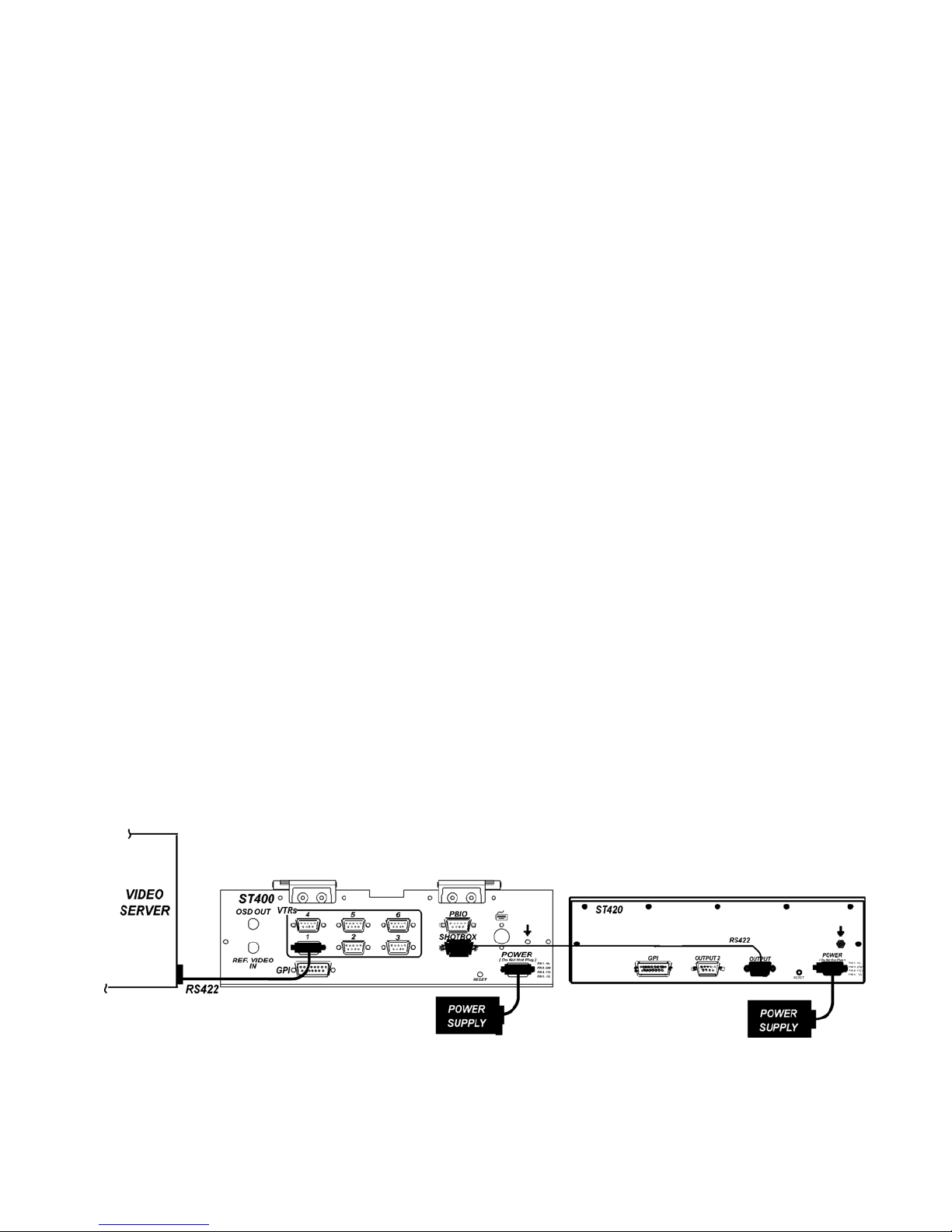
3. SYSTEM INSTALLATION
a. SHOTBOX
1) Plug one end of a standard 9-pin, RS422 serial cable into the OUTPUT
connector on the rear of the Shotbox. Plug the other end of the cable into
the “SHOTBOX” connector on the rear of the ST400.
2) Connect the supplied POWER SUPPLY, AULT#SW300, into the POWER connector
on the rear of the SHOTBOX. Plug the Power Supply into an outlet, 90 VAC – 240
VAC.
b. ST400-S/SM, VTR/DDR CONTROLLER
1) Plug one end of a 9-conductor, RS422 serial cable into the VTR1 (2, 3, 4, 5, or 6)
connector on the rear of the ST400. Plug the other end of the cable into the 9-pin
REMOTE connector on the Video Server.
2) Connect the supplied POWER SUPPLY, APX #4108, into the POWER connector on
the rear of the ST400. Plug the Power Supply into an outlet, 90 VAC - 240 VAC.
3) Check SETUP MENU prior to using the ST400 to confirm proper Record mode and
other User settable modes.
Attached House Video Reference cable to Ref. Video connector on the rear of the
ST400. Video Reference must be connected for frame accurate playout of ganged
channels, and for Capture function.
Installation is complete.
CONNECTION DIAGRAM

2044CL-O-EVS, 300 Clip Instant Access System, Odetics Protocol 7
4. VIDEO SERVER SETUP
a. Select ODETICS Broadcast communications protocol on the VIDEO SERVER to be
controlled.
b. Assign a serial port on the VIDEO SERVER through which the ST400 will control it.
NOTES: The VIDEO SERVER may not support LTC or VITC time modes in ODETICS
Broadcast mode. The ST400 will default to Tape Time if a non-supported time mode is selected.
In ODETICS Broadcast mode, the VIDEO SERVER may ONLY allow Full Record. INSERT and
ASSEMBLE record modes may be disabled.
5. LOAD A CLIP
ON THE ST400
a. Select a VTR by pressing VTR [1], [2], [3], [4], [5], or [6].
b. Press [CLIP LIST] to view the list of CLIP IDs that are resident on the Video Server.
The CLIP LIST indicator will turn on.
c. Press [CREATE] to create and load a new clip.
(Creating a clip is described in the CREATING A CLIP section.)
OR
Turn the Wheel to view the existing CLIP IDs on the video server.
Turn the Wheel clockwise to scroll forward, or counter-clockwise to scroll backward,
through the list of available CLIPs. Backward scrolling is limited to the last 10 screens of
CLIP IDs.
If the description was entered on the EVS server, it is displayed next to the CLIP ID.
Press [LOAD] to load the highlighted CLIP ID. After loading the selected clip, the CLIP
LIST function will terminate. The CLIP LIST indicator will turn off.
OR
Manually enter a Clip ID using the ST400 numeric keypad or Shotbox “QWERTY”
keyboard, or PC keyboard.
Press [LOAD] to load the entered CLIP ID for playout.
d. Repeat steps a - c to load clips on desired VTRs.

2044CL-O-EVS, 300 Clip Instant Access System, Odetics Protocol 8
6. LEARN A CLIP OR CLIP COMBINATION
a. ON THE ST400
1) Press VTR [1], [2], [3], [4], [5], or [6] to select the channel to learn.
2) Load a clip on the selected channel. See section LOAD A CLIP.
3) Use the transport functions to view the clip.
Press [IN] to mark an IN point. The IN LED will turn on.
On recall, the clip will cue to the IN time, not the beginning of the clip.
Optional: Press [OUT] to mark an OUT point. The OUT LED will turn on.
On recall, the clip will play to the OUT point then stop.
To delete an IN or OUT point, press and hold [DEL], then press [IN]or [OUT].
The IN/OUT LED will turn off.
If no IN point is marked, the current location of the clip will be learned as the IN
point.
4) For GANGs, repeat steps 1 and 2 for each channel.
Then, press the [GANG] softkey.
Press VTR [1], [2], [3], [4], [5], or [6] to add it to the GANG. The VTR LED
will turn on.
Press the VTR key again to remove it from the gang. The VTR LED will turn
off.
Press [ESC] to exit GANG mode. The LEDs of all GANGed VTRs will turn on.
b. ON THE SHOT BOX
1. Press [LEARN]. The LEARN indicator will turn on.
2. Select the desired BANK by pressing BANK [1], [2], [3], [4], [5], [6], [7], [8],
[9] or [0].
3. Press the desired Shotkey to complete the learn process.
The learned CLIP ID is displayed on the Shotkey.
4. Press [ESC] at anytime to escape without LEARNing.

2044CL-O-EVS, 300 Clip Instant Access System, Odetics Protocol 9
7. RECALL A CLIP OR CLIP COMBINATION
ON THE SHOTBOX
a) Select the desired BANK by pressing BANK [1], [2], [3], [4], [5], [6], [7], [8], [9] or [0].
The Shotkeys will display the assigned CLIP IDs for the selected bank.
b) Press the desired Shotkey.
The selected clip or clip combination will be loaded on the learned channels, and cued to
the learned IN point. The learned OUT point and GANG mode will be set.
8. RECUE CLIP
a. Press [RECUE]. If an IN Point is marked (the IN indicator is on), the clip will RECUE to
the IN Point.
If the IN point is not marked, the clip will RECUE to the start of the clip.
b. Press [CUE OUT] to cue to the marked OUT point.

2044CL-O-EVS, 300 Clip Instant Access System, Odetics Protocol 10
9. LEARN FROM THE ST400
a. ODETICS PROTOCOL
1) Press VTR [1], [2], [3], [4], [5], or [6] to select the channel to learn.
2) Use the transport functions to view the clip.
Press [IN] to mark an IN point. The IN LED will turn on.
On recall, the clip will cue to the IN time, not the beginning of the clip.
Optional: Press [OUT] to mark an OUT point. The OUT LED will turn on.
On recall, the clip will play to the OUT point then stop.
To delete an IN or OUT point, press and hold [DEL], then press [IN]or [OUT].
The IN/OUT LED will turn off.
If no IN point is marked, the current location of the clip will be learned as the IN
point.
3) For GANGs, repeat steps a and b for each channel.
Then, press the [GANG] softkey.
Press VTR [1], [2], [3], [4], [5], or [6] to add it to the GANG. The VTR LED
will turn on.
Press the VTR key again to remove it from the gang. The VTR LED will turn
off.
Press [ESC] to exit GANG mode. The LEDs of all GANGed VTRs will turn on.
4) Select the desired Cue Point by pressing [NEXT CUE], [LAST CUE] or by
manually entering the Cue Point using the numeric keypad, followed by
[ENTER].
The selected Cue Point number is shown on the bottom part of the display.
5) Press [SHIFT] + [LEARN] to initiate the LEARN.
The display will show: “Select VTRs to learn:--------”
6) Select the VTRs to learn by pressing VTR keys [1], [2], [3], [4], [5], and/or [6].
7) Press [LEARN] to complete the learn process.
Dieses Handbuch passt für folgende Modelle
1
Inhaltsverzeichnis
Andere DNF Controls Aufnahmegeräte Handbücher

Beliebte Aufnahmegeräte Handbücher anderer Marken


Strymon
Strymon NIGHTSKY Bedienungsanleitung

Mitsubishi Electric
Mitsubishi Electric 16CH DIGITAL RECORDER DX-TL5000U Bedienungsanleitung

Tews Technologies
Tews Technologies TPMC465 Bedienungsanleitung

Honeywell
Honeywell Excel 50 Bedienungsanleitung

SeaLevel
SeaLevel COMM+8.LPCI Bedienungsanleitung

Arturia
Arturia AUDIOFUSE STUDIO Bedienungsanleitung


