DriveCam DC3 Bedienungsanleitung

DRC232-A 2007-08-07 Page 1 DC3 with Pushbutton Installation Instructions
DC3 Video Event Recorder
with Pushbutton Installation Instructions
Installation of the event recorder is not complicated, but care must be taken to ensure successful
operation. Follow these instructions carefully to ensure proper orientation and operation.
1. Check the contents of the installation kit

DRC232-A 2007-08-07 Page 2 DC3 with Pushbutton Installation Instructions
2. Thoroughly clean and dry the glass
CAUTION: This step is critical to prevent the bracket from falling off at a later date.
Step 1 Select a mounting location on the windshield behind the rear view mirror
on the passenger side of the vehicle.
Step 2 Using the alcohol prep pad provided, thoroughly clean the mounting area.
Step 3 Using a clean, dry cloth, thoroughly dry the mounting area.

DRC232-A 2007-08-07 Page 3 DC3 with Pushbutton Installation Instructions
3. Carefully select the mounting location
The event recorder needs to be mounted in a location that provides an unobstructed view of the interior
and exterior (front) of the vehicle.
CAUTION: Do not peel the backing from the adhesive strip until instructed to do so.
Step 1 Loosen the Torx screws so the event recorder can rotate in the bracket.
Step 2 Pull the mirror down to its lowest position.
Most rear view mirrors can be adjusted up or down. Before selecting the mounting location,
adjust the mirror all the way down so that it can never cover the lens after mounting.
Step 3 Position the assembly behind the mirror, about one inch to the right of the post to allow
easy access to the Torx screw and power connection.

DRC232-A 2007-08-07 Page 4 DC3 with Pushbutton Installation Instructions
4. Mark the selected mounting location on the glass
Step 1 When you have selected the best mounting location, hold the assembly in place and trace
the outline of the bracket on the windshield with a felt tip marker.
Step 2 Make sure the traced guide marks are level before proceeding.
Step 3 Remove the event recorder from the mounting bracket.
Step 4 Check the fit of the bracket against the windshield.
If the windshield is curved, gently bend the bracket so that it will lie flush against the glass.

DRC232-A 2007-08-07 Page 5 DC3 with Pushbutton Installation Instructions
5. Attach the mounting bracket to the windshield
CAUTION: The adhesive is very sticky.
Once applied to the windshield, it will not easily come off.
Step 1 Make sure the glass is clean and dry and the air temperature is at least 50°F (10°C).
Step 2 Remove the backing from the adhesive side of the bracket.
Step 3 Start by placing only the top edge of the bracket against the windshield,
aligned with the guide marks, and make sure it is level.
Step 4 Press the bracket firmly against the windshield starting at the top
and pressing the sides downward.
Do not apply excessive pressure as it may cause the windshield to break.
Step 5 Make sure there are no large air bubbles under the bracket.
You may need to (carefully) apply additional pressure to the bracket and remove any large air
bubbles. Use a small pin to create an escape path for the air if the problem is persistent.

DRC232-A 2007-08-07 Page 6 DC3 with Pushbutton Installation Instructions
6. Route the RJ45 Interconnect Cable
CAUTION: When installing the interconnect cable in a vehicle with side or curtain airbags, be
certain that neither the cable, nor your installation activities, interferes with any
airbag related mechanisms or otherwise affects airbag deployment.
Step 1 Starting just above the rear view mirror, route the cable under the window trim or
headliner across to the door pillar.
Step 2 Route the cable down the door pillar underneath the vertical door / window trim.
Step 3 Route the cable out from underneath the trim and under the dashboard.
You may need to remove the trim to route the cable. When reinstalling, be careful not to damage
the trim clips or the cable. Keep the cable clear from sharp edges and moving parts.

DRC232-A 2007-08-07 Page 7 DC3 with Pushbutton Installation Instructions
7. Wiring Diagram (DC3 with Pushbutton Installation)
The RJ45 Interconnect Cable is 14 feet long with connectors (similar to telephone connectors) at each
end. One end of the cable plugs into the event recorder. It is then routed to a secure location under the
dashboard and plugged into the middle port of the Cable Access Terminal (CAT).
The Power I/O Cable is 2½ feet long. One end of the cable plugs into the right port of the CAT. At
the other end of the cable are five wires which connect to ground, vehicle power (continuous), and vehicle
power (ignition-switched) – this cable’s blue and white wires are not used when installing the Pushbutton.
The Pushbutton Cable is 4½ feet long. One end of the cable plugs into the left port of the CAT. At
the other end of the cable are two wires (blue & white) which connect to the Pushbutton.

DRC232-A 2007-08-07 Page 8 DC3 with Pushbutton Installation Instructions
8. Electrical connections (red, brown, & black wires)
These are the 3 required connections for the event recorder to function. The red wire provides primary
power and must be connected to a continuous power source. The brown wire is an ignition sense. It is
used by the event recorder to perform functions such as activating the IR Illuminator (see page 13) when
the vehicle ignition is switched on. The black wire is ground.
The RED WIRE must be connected to a 12V or 24V fused power source that is ALWAYS ON.
The BROWN WIRE must be connected to a 12V or 24V fused power source that is IGNITION–SWITCHED.
The BLACK WIRE must be connected to negative or to a clean GROUND.
The Power I/O cable’s BLUE & WHITE WIRES are not used when installing the Pushbutton. Cap these
two wires then coil and wrap them securely to the cable.
CAUTION: Check the vehicle manufacturer’s recommendations and guidelines
for proper installation and wiring of aftermarket devices.
Extending Wires: The power and ignition sense connections provide current limiting protection through
the Cable Access Terminal (CAT). However, any wire with power before reaching the CAT is not
protected. If wires need to be extended for any reason, extend the ground wire first. If you must extend
the red or brown wires, keep them as short as possible. If the extended length exceeds 16 inches, place
an inline fuse (1-3 Amp) between the extended wire and the power connection. The gauge of wire used
for any extension must be the same gauge (18 gauge) as the DriveCam power cable wires or larger. If
the extended wire length must exceed 20 feet, contact DriveCam for the recommended wire gauge.

DRC232-A 2007-08-07 Page 9 DC3 with Pushbutton Installation Instructions
9. Mount the event recorder in the bracket
Step 1 Plug the RJ45 Interconnect Cable into the event recorder.
Step 2 Place the event recorder in the bracket.
Step 3 Adjust the event recorder so that it hangs vertically (plumb).
Step 4 Secure the event recorder in the bracket using the 2 Torx screws and Torx wrench.
The Large Plastic Washer on the left side of the bracket is designed to partially cover the RJ45
Interconnect cable so that it cannot be unplugged by the driver. The plastic washers can be easily
removed from the metal bracket after removing the screws. Make sure the larger of the two washers is
on the left (power connection) side of the bracket.
Step 5 Plug the RJ45 Interconnect Cable and the Power I/O
Cable into the Connector Access Terminal (CAT).
The Pushbutton cable will also be plugged into the CAT
in Step 12. To avoid having to extend wires, locate the
CAT within 4½ feet of the Pushbutton mounting location.
Following installation, secure the CAT in a safe location
using a screw or zip-tie through its mounting hole.
DRC232-A 2007-08-07 Page 10 DC3 with Pushbutton Installation Instructions
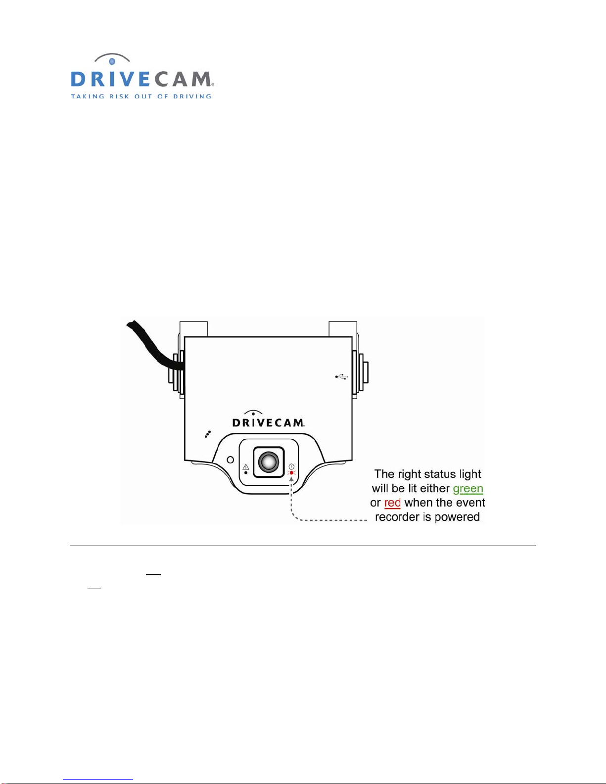
10. Test the red connection (continuous power)
Once power and ground connections are made, the LED status light to the right of the interior-facing lens
should be on (either a green or red light) when the vehicle’s engine is off and the key is removed from the
ignition.
Step 1 If the right LED is on, the event recorder is connected properly.
Step 2 If the right LED is not on, recheck the wiring connections and/or fuses.
* * * The right LED should remain on when the key is in any position * * *
The LED on the left of the lens will light (solid green) for about 30 seconds after power is first applied. If
the left LED does not turn off or if it begins flashing (either red or green), please call DriveCam Technical
Support for instructions.
NOTE: See pages 14 & 15 for detailed descriptions of the LED behavior (light patterns).
Andere Handbücher für DC3
1
Inhaltsverzeichnis
Andere DriveCam Dashcam Handbücher


