
DuraComm HE1U-5012-BC-MU Technisches Datenblatt
!1!"#!$%!&'(')*!%+!$,-.
/!
!
!"#$%&'#(%)*%+$,
!-./,"00-1-2314,#$,5*,67,8*,97:2;,<=>>?4,
@:32;A,B=-C2,
(These instructions are intended for use by a technician familiar with electronic products)
•Integrated Float Charge Circuit
•Integrated Low Voltage Disconnect
•Selectable Input Voltage 110 or 220 VAC
•Remote Monitoring of Power Supply Voltage and
Current, Battery Voltage and Current, and an External
Alarm.
•Remote control of power supply ON/OFF and External
Alarm output ON/OFF via Web Interface
•Short Circuit / Overload / Over Voltage / Over
Temperature Protection
•Manual Battery Disconnect Switch
•3 year warranty
DESCRIPTION
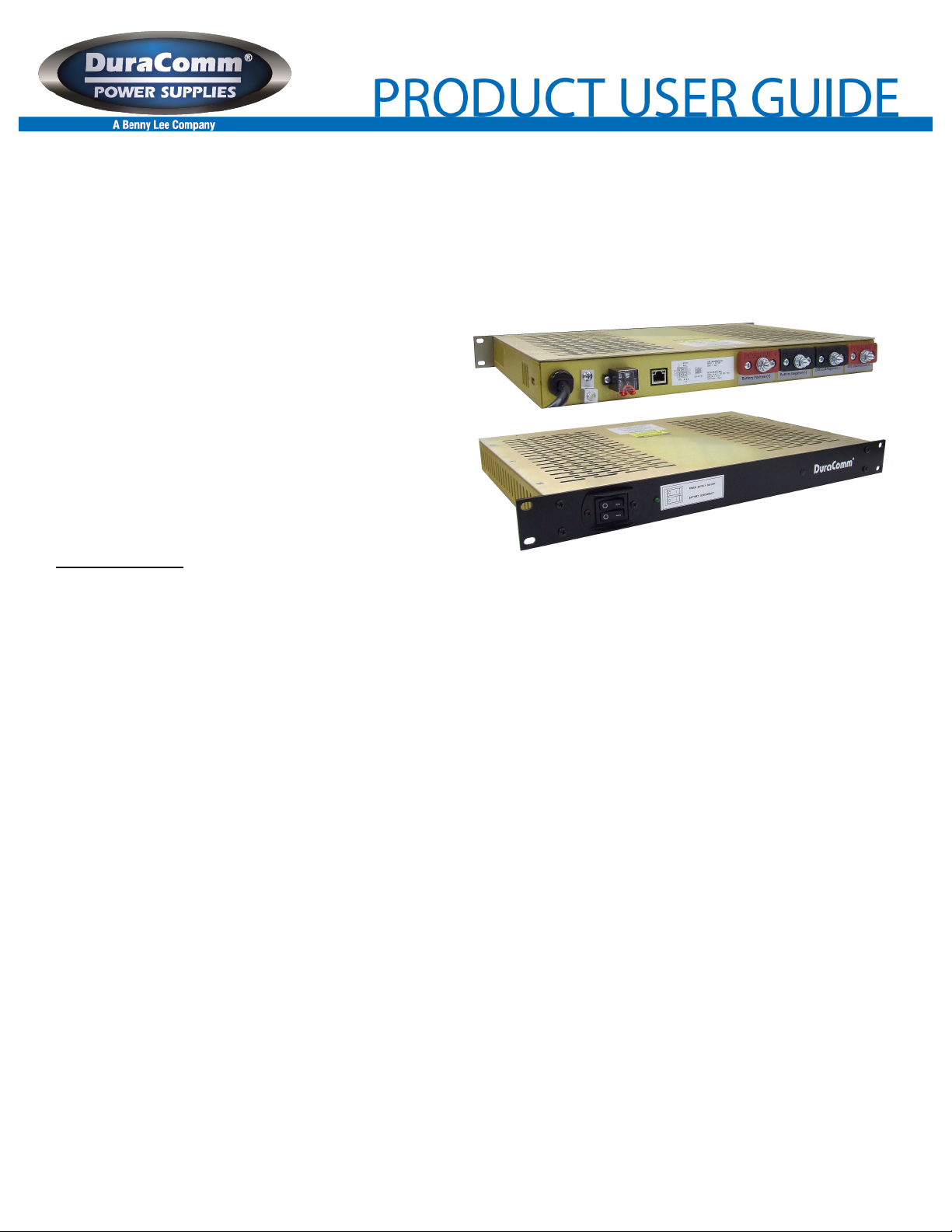
The HE1U-5012-BC-MU is a Heavy Duty AC to DC 750 Watt Power Supply, a low voltage disconnect, and a float charge
circuit in a 1U chassis. The HE1U-5012-BC-MU comes with power factor correction, and four layers of protection against overload, over
voltage, over temperature, and short circuit. This model also comes with a manual battery disconnect switch, internal power supply
ON/OFF remote control, and DC-OK. The HE1U-5012-BC-MU comes with a 3 year warranty.
The new internal Remote Monitoring and Control Unit (RMCU), provides the ability to remotely monitor the AC voltage, power
supply current and voltage, battery voltage and current, and internal temperature, as well as the ability to remotely control the ON/OFF
State of the power supply unit, all via the internet using any standard web browser. A mobile-friendly version of the status page is also
included.
Users that have access to the network can view the status of the power supply, control outputs, and the alarm conditions, as
well as download a .CSV file of logged states. Administrative users can access the setup screens and change the control settings by
logging into the RMCU via the browser. Alarm conditions are configurable, and can include over and under thresholds. Alarm
notifications can be configured by an administrator to send email and SNMP traps. Setups are saved in non-volatile RAM, and a battery
backed up real-time clock is provided to timestamp information logged to the internal SD card. Logging rate is user settable.
The HE1U-5012-BC-MU comes with the DuraComm three-year warranty.
!

!2!"#!$%!&'(')*!%+!$,-.
SPECIFICATIONS
Output Voltage........................................................................................................................................................................ 13.8 VDC
Output Voltage Tolerance............................................................................................................................................................+/- 1 %
Output Amperage ............................................................................................................................................................ 50 Amps max.
Maximum Power, continuous .................................................................................................................................................750 Watts
Maximum Ripple and Noise..........................................................................................................................................150 mV p-p max
Input Voltage, Switch Selectable .................................................................................................................................. 110-or 220 VAC
Input Frequency Range ........................................................................................................................................................... 47-63 Hz
Maximum AC Current ..............................................................................................................8.2 Amps/115 VAC; 3.9 Amps/230 VAC
Typical Efficiency............................................................................................................................................................................89 %
Max Inrush Current, single cycle ............................................................................................25 Amps / 115 VAC, 40 Amps / 230VAC
Short Circuit Protection.................................................................................................................................. Constant Current Limiting
Overload Protection (operates) ................................................................................................................................. typical 105-125%
Line Regulation.........................................................................................................................................................................+/- 0.5 %
Load Regulation .......................................................................................................................................................................+/- 0.5 %
Fan Control.................................................................................................................................... Heat sink temp >140 F (60 C) = ON
Over Temperature ........................................................................................................................ >195 F (90 C) auto output shutdown
Rise Time following ON ................................................................................................................................................................50 mS
Hold Time following OFF ..............................................................................................................................................................10 mS
Working Temperature Range ............................................................................................................. -22 F to +158 F (-30 C to +70 C)
Storage Temperature ......................................................................................................................... -40 F to +185 F (-40 C to +85 C)
Withstand Voltage ..................3 KVAC @ 10 ma (I/P-O/P)/1 min, 2 KVAC @ 10 ma (I/P-FG)/1 min, 500 V @ 10 ma (O/P-FG)/1 min
Dimensions....................................................................................................................................................... 1.75” H x 19” W x 14” D
Weight ......................................................................................................................................................................................... 9.1 lbs
RMCU SPECIFICATIONS
Hardware Revision ............................................................................................................................................................................ 2.0
Firmware Revision............................................................................................................................................................................. 2.7
Network Connector............................................................................................................. RJ-45 (10/100 Ethernet) with activity LEDs
Backup Battery ..........................................................................................................................................................................CR2032
Memory Card................................................................................................................................................................... 4GB Micro SD
Voltage Measurement Range...................................................................................................................................0 VDC to 100 VDC
Current Measurement Range ................................................................................................................................0 Amps to 100 Amps
Digital Alarm input ........................................................................................................................................ Normally Closed Contacts
Alarm Output ...................................................................... Open Collector, 60 VDC Max (REV 2 RMU Hardware), 500 mA sink Max
Alarm Response Time .................................................................................................................................................................250ms
Alarm Notifications.................................................................................................................................................. Email and/or SNMP
Logging Rate .............................................................................................................................1 minute resolution, 1 minute to 1 hour
Log Download Format ............................................................................................................... .Comma Separated Values (CSV) File
SNMP MIB File ............................................................................................................................... Download from Device Setup Page
5V Supply Maximum Current...............................................................................................................................................300 mAmps
BATTERY BACK UP & CHARGER
Maximum Power, continuous .................................................................................................................................................750 Watts
Auto-revert to battery or power supply ..................................................................Provided by dual Shottky diode in OR configuration
Maximum output current in battery mode ........................................................................................75 amps (limited by Shottky diode)
Maximum charge voltage ....................................................................................................................................................... 13.8 VDC
Maximum recharge rate................................................................................................................................................................ 2 amp
Note: The battery charger is a fixed resistance type that provides a tapering current output. A float charge current of 1-2 amps will
be maintained after the battery is charged.
!3!"#!$%!&'(')*!%+!$,-.
LOW VOLTAGE DISCONNECT with RELAY
Maximum Interrupt Current / continuous current ................................................................................................................75 Amps DC
Disconnect Voltage................................................................................................................................................................. 10.5 VDC
Reconnect Voltage ................................................................................................................................................................. 12.5 VDC
Disconnect Delay.......................................................................................................2 minutes @ less than preset disconnect voltage
INSTALLER NOTES
NOTE: DO NOT block any of the cooling vents on the sides and top and always allow adequate ventilation by not installing the unit
inside tightly closed spaces. Physical mounting position is not critical but the cooling vents must not be blocked.
NOTE: The outputs are NOT referenced to the chassis. The Modular System can be used either positive or negative ground.
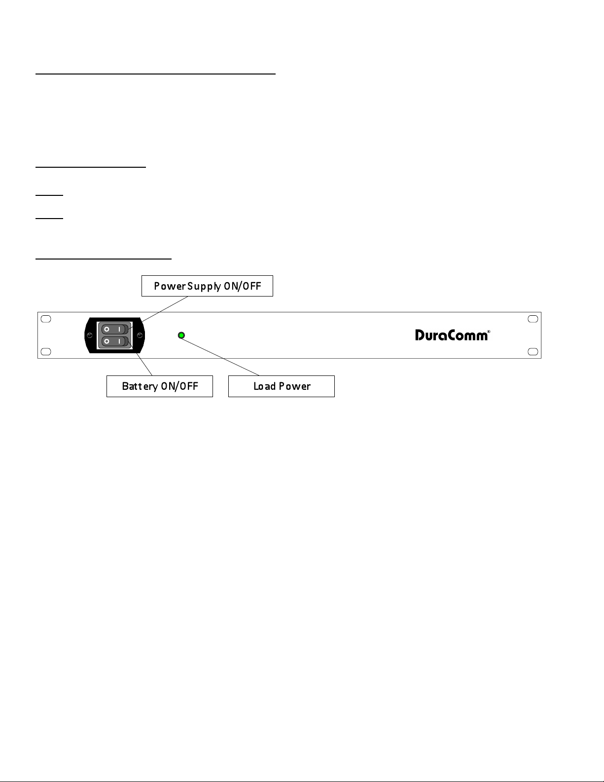
FRONT PANEL LAYOUT
!4!"#!$%!&'(')*!%+!$,-.
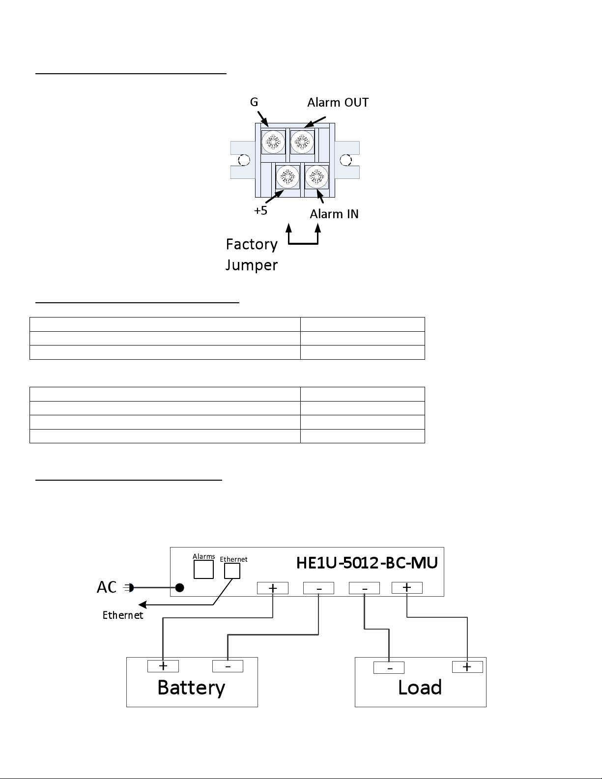
INSTALLATION BLOCK DIAGRAM
!
HE1U-5012-BC-MU Alarm Connector
Between +5V and Alarm In
Output Status
Switch Closed
Alarm Closed
Switch Open
Alarm Open
Between G and Alarm Out
Output Status
Open-Drain
500 mA max, 60 V max
Alarm ON/LOW
Shorted
Alarm OFF/HIGH
Open
HE1U-5012-BC-MU Wiring Layout
This system setup will provide continuous power to the load and maintain the battery bank with a float charge circuit while AC
power is on. There is a seamless transfer of the load to the battery when the AC power goes off. The LVD will disconnect the battery if
the voltage drops below 10.5 VDC. The battery reconnects once AC power is restored and voltage reaches 12.5 VDC.

!5!"#!$%!&'(')*!%+!$,-.

!6!"#!$%!&'(')*!%+!$,-.
CONNECTING TO THE HE1U-5012-BC-MU VIA THE INTERNET
Prerequisites
01)*23!453676)*84*"8)!3')*!529652!:;2*;28!*;2!<=->?@,-$?AB?C>!:6DD!"E284*2!"7!*;2!72*:"8F!:6*;!G<BH!"8!4!#6I25!JH!
45582))K!L;2!#49*"81?)2*!<=->?@,-$?AB?C>!:6DD!;4M2!*;2)2!)*4*69!45582))2)N!D9,ECC;2AAF,#G(H#IJH#''H(('K,.E62:E4,
ECC;2AAF,#G(H#IJH#''H#K,326LEAMF,(&&H(&&H(&&H'K,E3C,8N<,ECC;2AAF,#G(H#IJH#''H#K!
J#!1"'!9"7#6('82!6*!*"!')2!G<BH+!*;2!<=->?@,-$?AB?C>!:6DD!82O'2)*!47!4M46D4PD2!JH!45582))!"7!1"'8!72*:"8FK!Q"'!:6DD!
7225!*"!52*283672!:;4*!45582))!6*!;4)!P227!(6M27K!
J#!G<BH!6)!7"*!')25+!)1)*23!453676)*84*"8)!3')*!4D)"!9;"")2!47!'7')25!JH!45582))+!475!"*;28!72*:"8F!)2**67()!*"!')2!67!
*;2!R2*:"8F!02*'E!)98227K!01)*23!453676)*84*"8)!:6DD!4D)"!7225!*"!9;"")2!47!2346D!)28M692!475!45582))!*"!')2!#"8!
7"*6#694*6"7)+!6#!722525K!L;2)2!:6DD!P2!')25!67!*;2!=346D!02*'E!098227K!
DETERMINING THE IP ADDRESS OF THE HE1U-5012-BC-MU
H":28!'E!*;2!<=->?@,-$?AB?C>!*;27!9"7729*!*;2!<=->?@,-$?AB?C>!*"!*;2!72*:"8F!:6*;!47!=*;2872*!94PD2K!
Using DHCP
Q"'!:6DD!7225!*"!(2*!*;2!JH!45582))!67!"72!"#!*:"!:41)K!Q"'!947!(2*!*;2!JH!45582))!#8"3!*;2!G<BH!)28M28S)!9D627*!D6)*+!"8!
1"'!947!')2!4!HB!"7!*;2!)432!72*:"8F!*"!)947!#"8!*;2!72:!JH!45582))!P1!')67(!4!)"#*:482!*""D!)'9;!4)!&7(81!JH!0947728K!
J7!&7(81!JH!0947728+!1"'!);"'D5!455!*;2!C&B!45582))!TU2*9;28V!'7528!TL""D)!W!U2*9;28)VK!L;2!G'84B"33!C&B!
45582))2)!4DD!)*48*!:6*;!4!P4)2!45582))!"#!O'%)P%8&%I)%PH,X86*2!5":7!*;2!JH!45582))!"#!*;2!<=->?@,-$?AB?C>+!*;27!
E8"9225!*"!*;2!)29*6"7!67!*;6)!347'4D!74325!T@>23,E,Q2R,*733216-73,67,6/2,!"#$%&'#(%)*%+$VK!
Using Static HE1U-5012-BC-MU IP and Network Configuration
J#!1"'8!72*:"8F!6)!7"*!)2*!'E!#"8!G<BH+!1"'!:6DD!7225!*"!347'4DD1!9"7#6('82!*;2!)2**67()!*"!34*9;!*;2!72*:"8F!6*!:6DD!P2!
')25!"7K!A2#"82!1"'!947!5"!*;4*+!1"'!:6DD!7225!*"!9"7#6('82!4!9"3E'*28!*"!*4DF!*"!*;2!<=->?@,-$?AB?C>!4*!*;2!52#4'D*!
9"7#6('84*6"7!)2**67()!);":7!4P"M2K!X2!:6DD!')2!X675":)!Y!4)!47!2I43ED2K!Z*;28!"E284*67(!)1)*23)!:6DD!M481+!P'*!*;2!
"M284DD!9"792E*!6)!*;2!)432K!
-K G6)9"7729*!1"'8!HB!#8"3!4DD!72*:"8F)K!
$K B"7729*!6*!56829*D1!*"!*;2!!:6*;!47!=*;2872*!94PD2![Q"'!341!7225!*"!')2!47!=*;2872*!98"))"M28!94PD2!6#!*;2!HB!5"2)!7"*!
4'*"34*694DD1!52*29*!*;6)!9"7#6('84*6"7\K!
%K ZE27!*;2!9"7*8"D!E472D!"7!1"'8!HB!475!)2D29*!T]62:!R2*:"8F!0*4*')!475!L4)F)V!
^K BD69F!"7!TB;47(2!&54E*28!02**67()V!"7!*;2!D2#*!)652!"#!*;2!)98227K!
@K _6(;*!9D69F!"7!T`"94D!&824!B"7729*6"7V!475!9D69F!"7!TH8"E28*62)V!
.K BD69F!"7!TJ7*2872*!H8"*"9"D!]28)6"7!^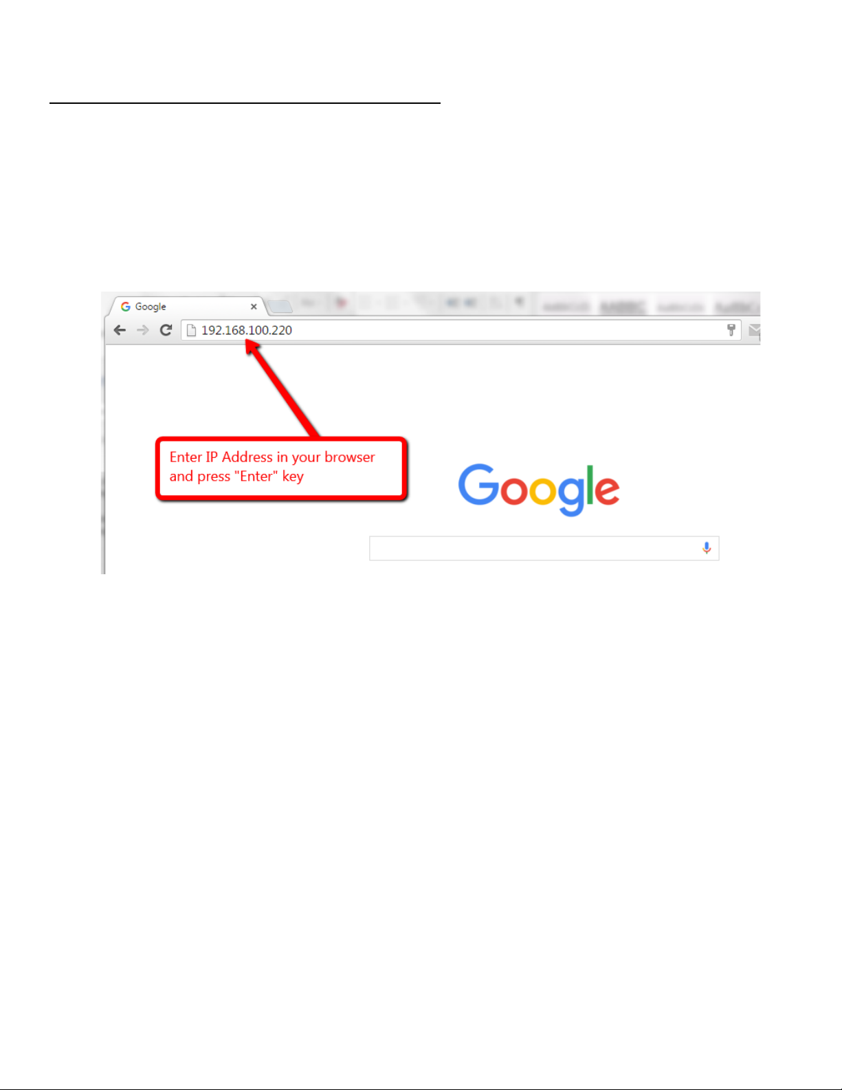
!7!"#!$%!&'(')*!%+!$,-.
Open a Web Connection to the HE1U-5012-BC-MU
!
-K B"7729*!*;2!_d?^@!9"7729*"8!"7!*;2!P49F!"#!*;2!<=->?@,-$?AB?C>!*"!1"'8!72*:"8F!
$K >)2!1"'8!#4M"86*2!52M692!475!P8":)28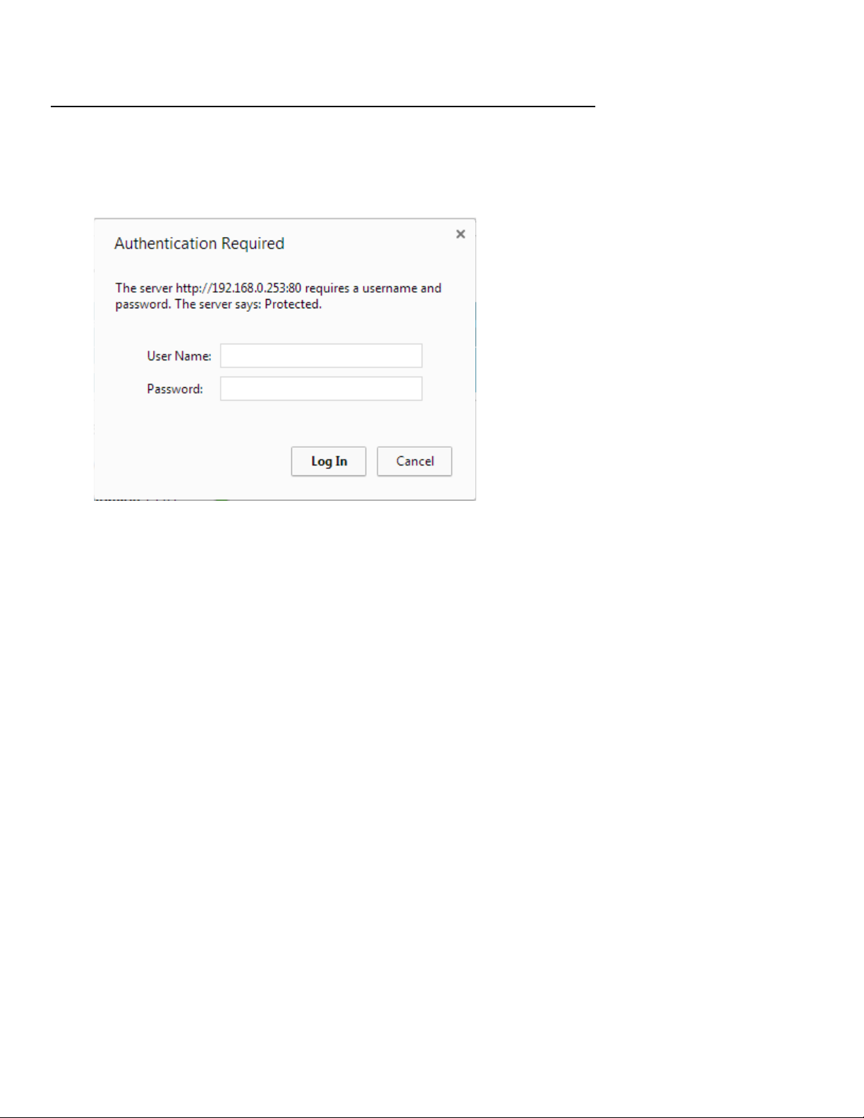
!8!"#!$%!&'(')*!%+!$,-.
REMOTE MONITORING AND CONTROL (HE1U-5012-BC-MU) SETUP
All setup requires an administrative user to log into the HE1U-5012-BC-MU in your power supply. Click the ‘Login’ button in the top
menu.
User Login
Enter the user name and password. Factory default username and password are as follows:
Admin Users have full control of the device.
Username: admin (cannot be changed)
Password: admin
Control users have limited control capability.
Username: control (cannot be changed)
Password: control
These two users are the only ones available in the HE1U-5012-BC-MU. “Control” users can access all screens except the User Setup
screen.
!9!"#!$%!&'(')*!%+!$,-.
NETWORK SETUP

!10!"#!$%!&'(')*!%+!$,-.
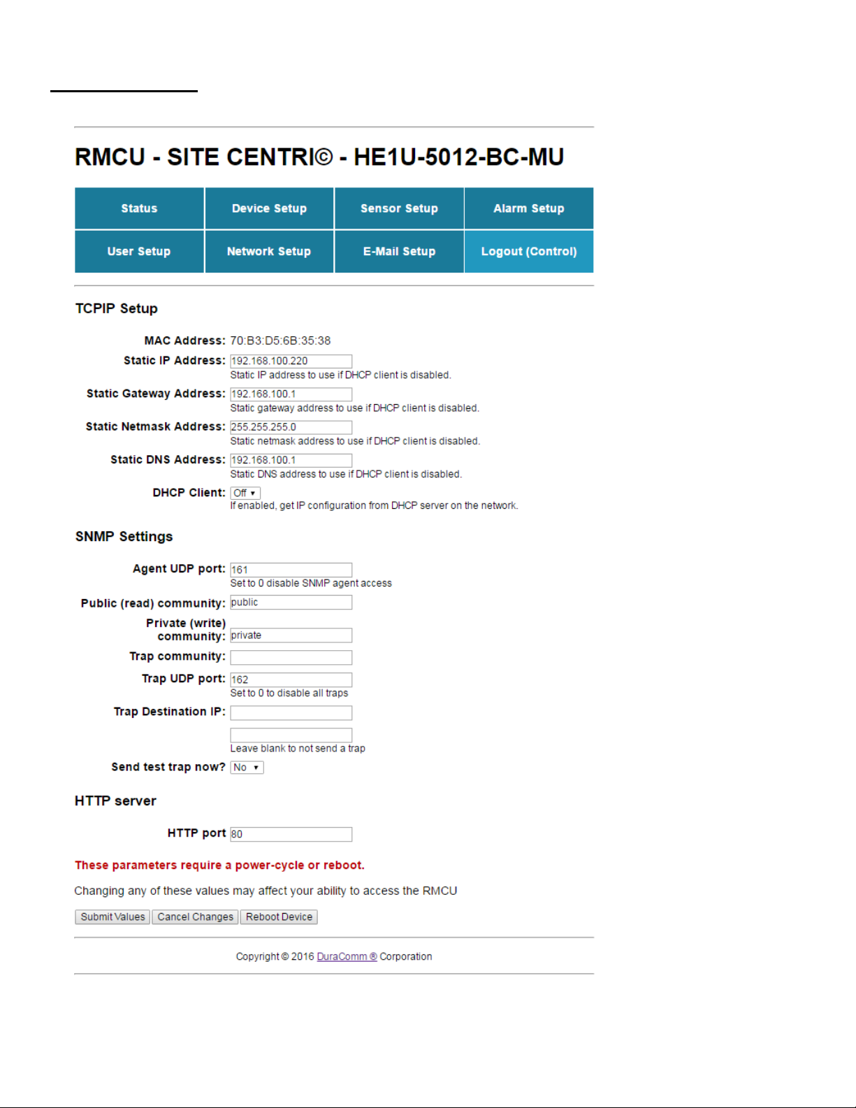
Network Setup
&!72*:"8F!453676)*84*"8!#"8!1"'8!9"3E471!3')*!9;"")2!*;2!)2**67()!#"8!*;6)!E4(2K!L;2!52#4'D*!<LLH!E"8*!6)!J'K!J#!4!
56##2827*!<LLH!E"8*!6)!')25+!6*!:6DD!7225!*"!P2!45525!*"!*;2!>_`!*"!4992))!*;2!_`H?b-$?C>K!U"8!2I43ED2N!6#!*;2!E"8*!6)!
9;47(25!*",J'J'!*;27!*;2!45582))!:"'D5!P2!9;47(25!*"!/66>FVV#G(H#IJH'H(&PFJ'J',,
_2M6)6"7!$K.!UX!#6I25!4!P'(!:6*;!)4M67(!*;2!0*4*69!R2*34)F!&5582))K!
N@W"F,X7=,L=A6,;2R776,6/2,C2Y-12,07;,1/E3.2A,-3,6/2A2,A266-3.A,67,6EM2,200216H
SNMP TRAPS SETUP
L;6)!)29*6"7!6)!)63ED6#625+!475!3247*!#"8!72*:"8F!453676)*84*"8)!:;"!4D82451!'7528)*475!0RCH!*84E)!475!;":!*"!
9"7#6('82!94E4PD2!2O'6E327*!67*"!*;268!)1)*23K!U"8!*;")2!:;"!:47*!*"!'7528)*475!*;2!P272#6*)!"#!')67(!0RCH!*84E)+!
1"'!947!)2489;!#"8!*846767(!34*2864D!"7D672!'7528!T0RCH!L84E)V+!TCJA!A8":)28)V+!475!T0RCH!C"76*"867(VK!
L;2!CJA!#6D2!#"8!*;2!<=->?@,-$?AB?C>!947!P2!5":7D"4525!#8"3!*;2!<=->?@,-$?AB?C>!4#*28!1"'!9"7729*!*"!6*!:6*;!
1"'8!P8":)28K!e"!*"!*;2!G2M692!02*'E!E4(2!475!D"(!67!*"!*;2!<=->?@,-$?AB?C>K!<4D#:41!5":7!*;2!E4(2!*;282!6)!4!D67F!
*"!*;2!CJA!#6D2K!_6(;*!9D69F!"7!*;2!D67F!475!9D69F!T04M2!`67F!&)V!*"!5":7D"45!*;2!#6D2K!!
&#*28!5":7D"45+!63E"8*!*;2!CJA!#6D2!67*"!1"'8!CJA!P8":)28!"8!C"76*"867(!)"#*:482!*"!9"7#6('82!6*!#"8!')2!:6*;!*;2!<=->?
@,-$?AB?C>K!
X;27!*;2!CJA!#6D2!;4)!P227!D"4525+!9"3ED2*2!*;2!T0RCH!02*'EV!)29*6"7!"7!*;2!TR2*:"8F!02*'EV!E4(2!"#!*;2!<=->?
@,-$?AB?C>!*"!9"7#6('82!6*!#"8!')2!:6*;!1"'8!3"76*"867(!)"D'*6"7K!
L;2!<=->?@,-$?AB?C>!:6DD!)275!*84E)!#"8!4DD!9"7#6('825!4D483!9"756*6"7)!679D'567(!P""*'E+!*23E284*'82+!474D"(!4D483)+!
475!56(6*4D!4D483)K!
G6(6*4D!Z'*E'*)!947!4D)"!P2!9"7*8"DD25!P1!0RCH!"7!*;2!<=->?@,-$?AB?C>K!
Inhaltsverzeichnis
