
DUROMAX XP4400EH Bedienungsanleitung
OWNERS MANUAL
Product Support
Product Information, Application, Service Info & Warranty
Questions
or call (800) 629-3325 Monday –Friday 6:00 am –6:00 pm (PST)

2
TABLE OF CONTENTS
TABLE OF CONTENTS
FEATURES
SAFETY INFORMATION
COMPONENT IDENTIFICATION
PREPARING THE GENERATOR
STARTING THE GENERATOR GASOLINE
STARTING THE GENERATOR PROPANE
USING THE GENERATOR
WATTAGE REFERENCE CHART
MAINTENANCE
Service Schedule
Checking the Oil
Changing the Oil
Air Cleaner Maintenance
Fuel Filter Cup Cleaning
Spark Plug Maintenance
Emptying the Gas Tank
Storage and Transportation
GENERATOR SPECIFICATIONS
TROUBLESHOOTING
WHEEL KIT ASSEMBLY
SERVICE INFORMATION
Changing/Inspecting the Carbon Brush
Changing/Inspecting the AVR
Maintenance Log
Wiring Diagram
Parts Lists
2
3
4 - 6
7 - 9
9 - 12
13
14
15 - 18
16
19
20
21
22
22
23
23
24
25
26
27
28
29
30
31
32-35

3
FEATURES
Dual Fuel Option, LPG or Gasoline.
Durable 7.0 HP, Air Cooled Overhead Valve Engine.
Heavy Duty Steel Frame with Four Point Fully Isolated Motor Mounts for Smooth
and Quiet Operation.
Wheel and Handle Kit for Easy Transporting.
Full Power Panel with Engine Shutoff Switch, Volt Meter, Circuit Breaker, and
Power Outlets.
(2) Fully Protected 120V Outlets & (1) 120V/240V Twist-Lock Outlet.
8 Hour Run Time.
All Steel 4.0 Gal. Fuel Tank with EZ-Read Gauge.
Low Oil Shut-Off Protects Engine.
Super Quiet Muffler Reduces Engine Noise.
Meets EPA Emission Standards.
This manual provides information regarding the operation and maintenance of these
products. We have made every effort to ensure the accuracy of the information in this
manual. We reserve the right to change this product at any time without prior notice.
Notice Regarding Emissions
Engines that are certified to comply with U.S. EPA emission regulations for SORE
(Small off Road Equipment), are certified to operate on regular unleaded gasoline, and
may include the following emission control systems: (EM) Engine Modifications and
(TWC) Three-Way Catalyst (if so equipped).

4
GENERAL SAFETY PROCEDURES
Please familiarize yourself with the following safety symbols and words:
The safety alert symbol is used with one of the safety words (DANGER, CAUTION, or
WARNING) to alert you of hazards. Please pay attention to these hazard notices both in
this manual and on the generator.
DANGER: Indicates a hazard that will result in serious injury or death if instructions are
not followed.
WARNING: Indicates a strong possibility of causing serious injury or death if
instructions are not followed.
CAUTION: Indicates a possibility of personal injury or equipment damage if instructions
are not followed.
DANGER: This generator produces poisonous carbon monoxide gas when
running. This gas is both odorless and colorless. Even if you do not see or smell
gas, carbon monoxide may still be present. Breathing this poison can lead to
headaches, dizziness, drowsiness, and eventually death.
Use outdoors ONLY in non-confined areas.
Keep several feet of clearance on all sides to allow proper ventilation of
the generator.
WARNING: The exhaust from this product contains chemicals known to the
State of California to cause cancer, birth defects, or other reproductive harm.
WARNING: This generator may emit highly flammable and explosive gasoline
vapors, which can cause severe burns or even death. A nearby open flame can
lead to an explosion even if not directly in contact with gas.
Do not operate near an open flame.
Do not smoke near generator.
Always operate on a firm, level surface.
Always turn generator off before refueling. Allow generator to cool for at
least 2 minutes before removing fuel cap. Loosen cap slowly to relieve
pressure in tank.
Do not overfill gas tank. Gas may expand during operation. Do not fill to
the top of the tank.
Always check for spilled gas before operating.
Empty the gasoline tank before storing or transporting the generator.
Before transporting, turn fuel valve to the off position and disconnect the
spark plug.

5
GENERAL SAFETY PROCEDURES (Continued)
WARNING: This generator produces a powerful voltage, which can result in
electrocution.
ALWAYS ground the generator before using it (see the "Grounding the
Generator” portion of the "PREPARlNG THE GENERATOR FOR USE
section).
Generator should only be plugged into electrical devices, either directly or
with an extension cord. NEVER connect to a building electrical system
without a qualified electrician. Such connections must comply with local
electrical laws and codes. Failure to comply can create a backflow of
power, which may result in serious injury or death to utility workers.
Use a ground fault circuit interrupter (GFCI) in highly conductive areas
such as metal decking or steel work. GFCls are available in-line with some
extension cords.
Do not use uncovered in rainy or wet conditions.
Do not touch bare wires or receptacles (outlets).
Do not allow children or non-qualified persons to operate.
WARNING: This generator produces heat when running. Temperatures near
exhaust can exceed 150°F (65°C).
Do not touch hot surfaces. Pay attention to warning labels on the
generator denoting hot parts of the machine.
Allow generator to cool several minutes after use before touching engine
or areas which heat during use.
CAUTION: Misuse of this generator can damage it or shorten its life.
Use the generator only for its intended purposes.
Operate only on dry, level surfaces.
Allow generator to run for 3 - 5 minutes before connecting any electrical
devices.
Shut off and disconnect any malfunctioning devices from generator.
Do not exceed the Wattage capacity of the generator by plugging in more
electrical devices than the unit can handle (see "PRECAUTIONS-
OVERLOADING THE GENERATOR").
Do not turn on electrical devices until after they are connected to the
generator.
Turn off all connected electrical devices, and turn off the breaker, before
stopping the generator.
6
GENERAL SAFETY PROCEDURES (Continued)
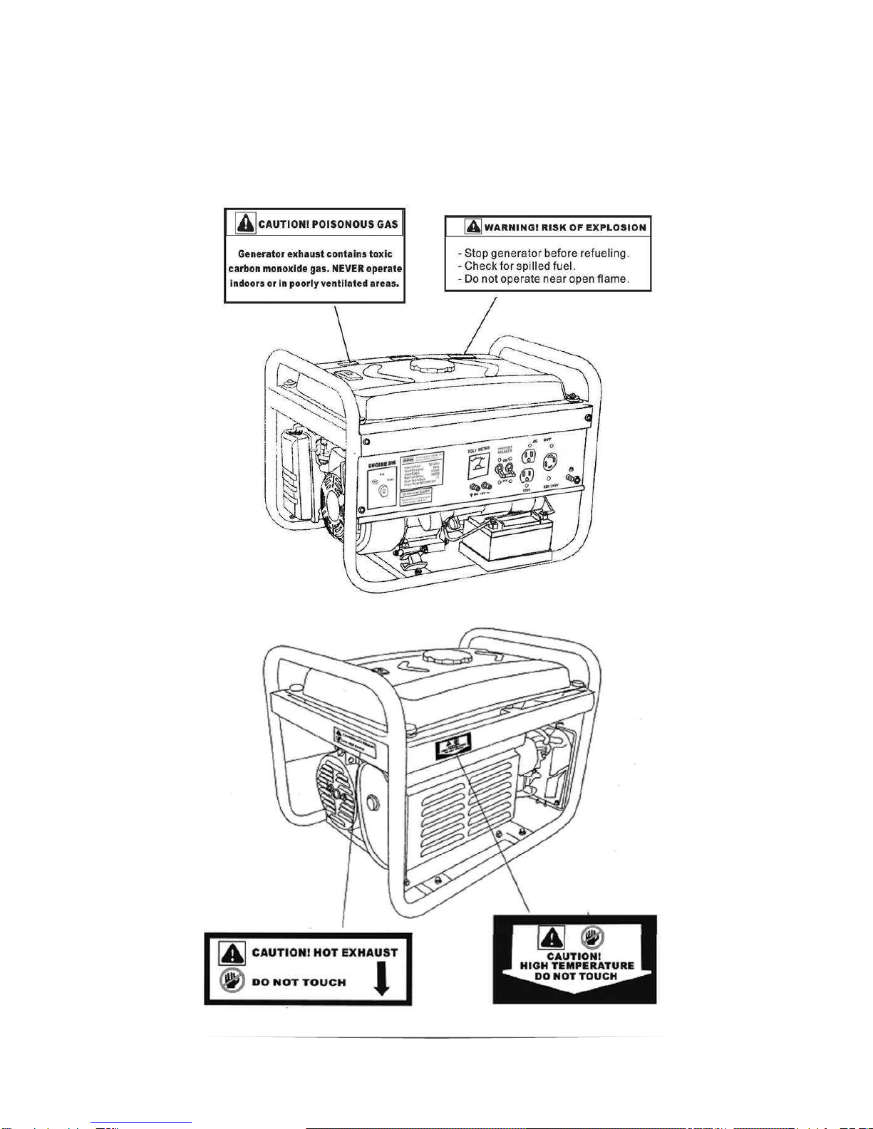
In addition to the above safety notices, please familiarize yourself
with the safety and hazard markings on the generator.
7
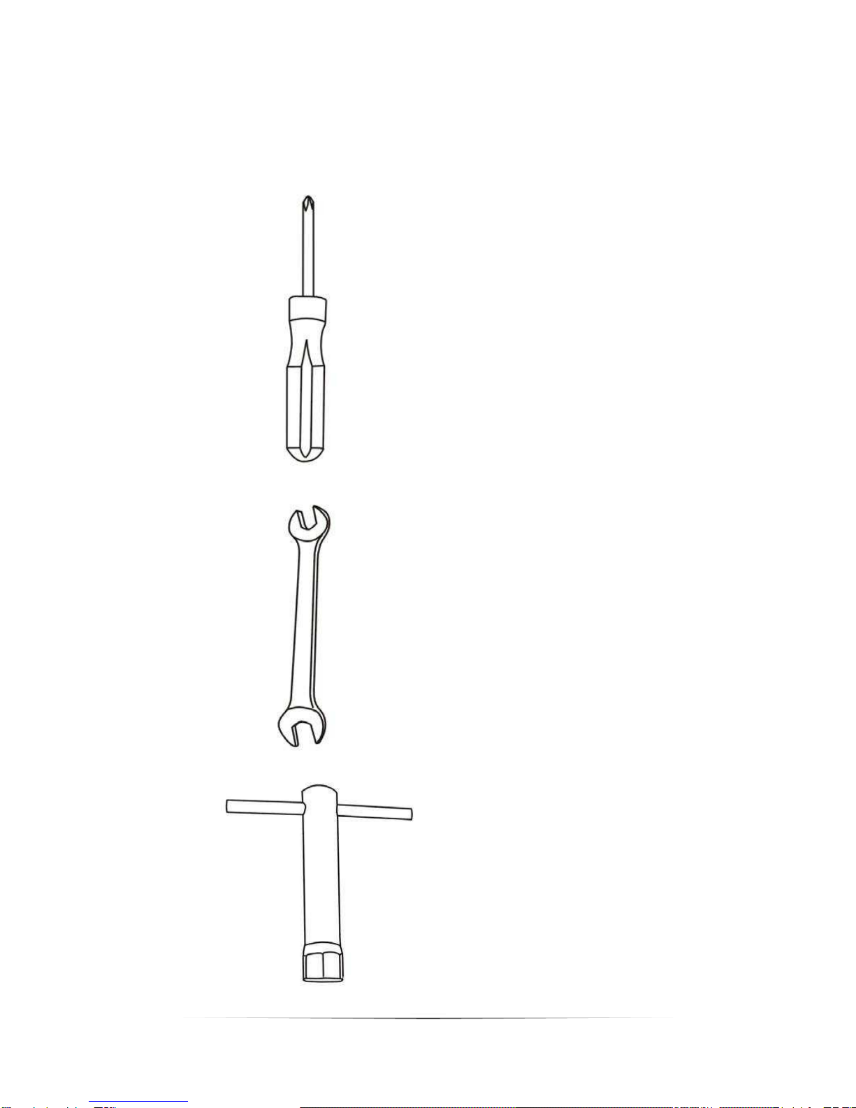
PACKAGE CONTENTS
Your generator comes with the items listed below. Please check to see that all of the
following items are included with your generator.
Screw driver
Spanner
Spark plug wrench
8
GENERATOR COMPONENTS
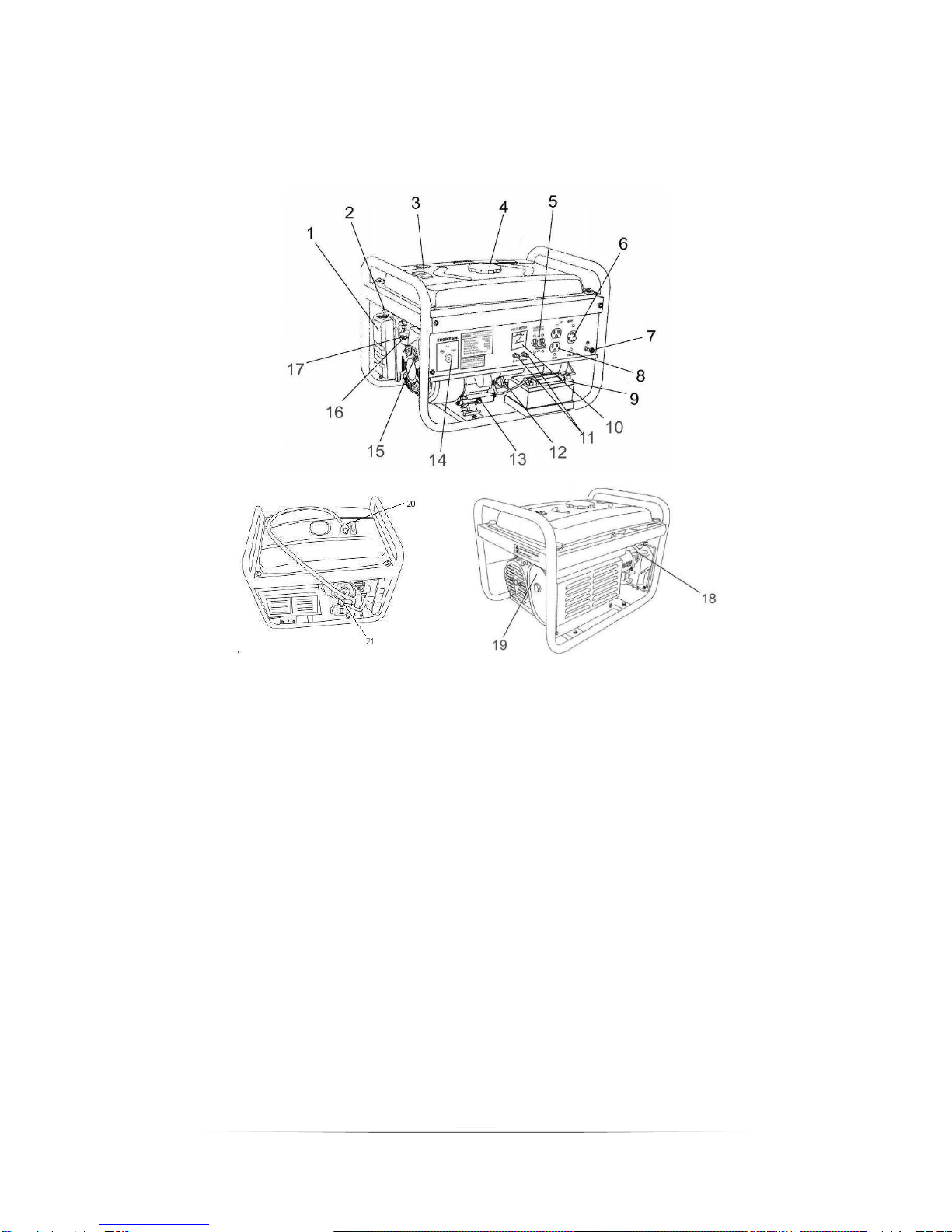
Please familiarize yourself with the locations and functions of the various components and
controls of your generator.
.
1. Air Cleaner - a removable, cleanable, oiled, sponge-like element that cleans the air
going into the engine.
2. Choke Lever - Allows the airflow into the carburetor to be restricted to assist in
starting the engine.
3. Fuel Gauge - Indicates the amount of fuel in the gasoline tank.
4. Fuel Cap - Allows access to fill the gasoline tank.
5. Circuit Breaker - Resettable switch that protects the generator from electrical
overload.
6. 120/240v 4-Prong Receptacle - Use to connect electrical devices that run 120 or
240 Volt, 60Hz, single phase, AC current (NEMA L14-30).
7. Ground Terminal - Connect a ground wire here to properly ground the generator.
8. 120v 3-Prong Receptacle - Use to connect electrical devices that run 120 Volt, 60
Hz, single phase, AC current (NEMA 5-20).
9. Battery - 12V DC 7ah Battery that powers the Electric Start System.
10.Volt Meter - Provides reading of voltage output.
11.12v DC Charging Posts –DC Output for charging batteries or running small DC
powered items.
12.Oil Filler Cap - Use to add or check the oil.
13.Oil Fill and Dipstick - Use to add or check the oil.
14.Engine Switch –3 Position Switch to “Start”, “Run”, or turn “Off” the generator.
15.Recoil Start –Easy Pull Recoil Start to start the engine without the electric start.
9
GENERATOR COMPONENTS (Continued)
16.Fuel Filter Cup - Traps dirt and water in gasoline before it enters the engine.
17.Fuel Valve - On/Off Valve that allows fuel into the engine.
18.Spark plug –Provides ignition to the engine.
19.Muffler –Reduces engine emissions and reduces noise.
20.Propane Tank Connector and Hose –Connects the LPG tank to the LPG
Regulator.
21.Propane Regulator and Pressure Release Valve - Provides a regulated LPG Fuel
supply to the engine. (Intended for use with a LPG Source of 10 PSI or more.)
PREPARING THE GENERATOR FOR USE
Using the Generator for the First Time
If you are using the generator for the first time, there are a few steps you must take to prepare
it for operation.
Step 1 - Add oil
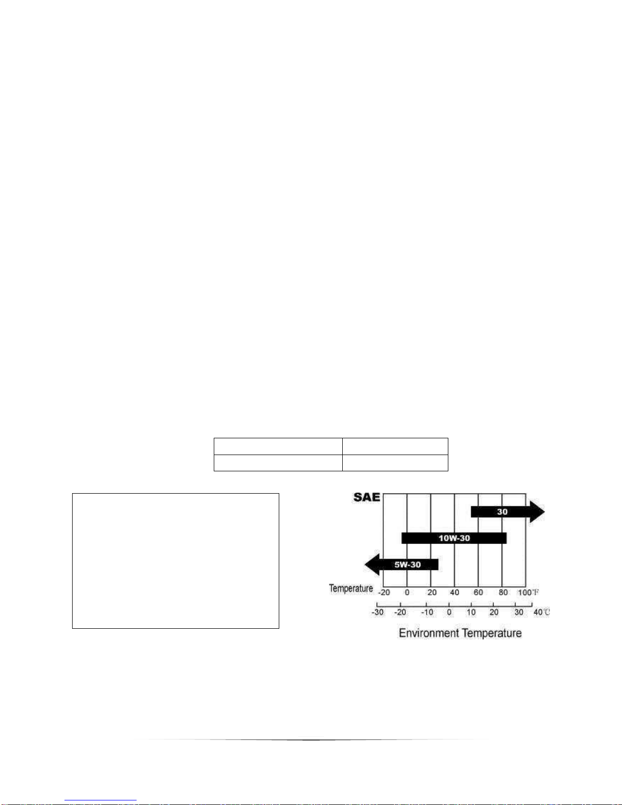
The generator requires engine oil to operate properly. The generator, when new from the
package contains no oil in the crankcase. You must add the proper amount of oil before
operating the generator for the first time. This amount, which is equal to the oil capacity of the
engine crankcase can be found on the chart in figure 1. When filling the engine with oil in the
future, please refer to this chart.
Model Number
XP4400EH
Engine Oil Capacity
20 fl. Oz. (0.6L)
Figure 1 –Generator Oil Capacity
• Do not apply engine oil with
additives or 2-stroke gasoline
engine oil. They don’t have enough
lubrication, and may shorten the
engine's service life.
• Engine oil recommended: SAE
10W-30. Viscosity varies with regions
and temperatures. Choose your oil
viscosity using the chart to the right.

10
PREPARING THE GENERATOR FOR USE (Continued)
Figure 2 –Unscrewing the Oil Cap Figure 3 –Adding Oil
To add Oil, follow these steps:
1. Make sure the generator is on a level surface.
2. Unscrew the oil filler/dipstick cap from the engine as shown in figure 2.
3. Using a funnel, add the appropriate amount of oil, as found in figure 1, into
the crankcase. You will know the crankcase is full when the oil level has
reached the lower lip of the opening you have just poured the oil into. (see
figure 3.)
4. Replace oil filler cap.
Step 2 - Add Gasoline
WARNING: Gasoline and gas fumes are highly flammable.
Do not fill tank near an open flame.
Do not overfill. Always check for fuel spills.
To ensure that the generator runs smoothly use only FRESH, UNLEADED GAS WITH
AN OCTANE RATING OF 87 OR HIGHER.
To add gasoline:
1. Make sure the generator is on a level surface.
2. Unscrew gas cap and set aside (NOTE: the gas cap may be tight and hard to
unscrew).
3. Slowly add unleaded gasoline to the fuel tank. Be careful not to overfill. Please
refer to the chart in figure 4 to find the gas capacity of your generator model. The
fuel gauge on the top of the gas tank indicates how much gasoline is in the
generator gas tank.
NOTE: Gas can expand. Do not fill the gas tank to the very top.
4. Replace fuel cap and wipe up any spilled gasoline with a dry cloth.
Andere Handbücher für XP4400EH
1
Inhaltsverzeichnis
Andere DUROMAX Wechselrichter Handbücher

DUROMAX
DUROMAX DUAL FUEL XP13000EH Bedienungsanleitung

DUROMAX
DUROMAX XP10000EH Bedienungsanleitung

DUROMAX
DUROMAX Duro Star DS4000S Bedienungsanleitung

DUROMAX
DUROMAX XP12000EH Bedienungsanleitung

DUROMAX
DUROMAX DuroStar DUAL FUEL DS10000EH Bedienungsanleitung

DUROMAX
DUROMAX XP5500EH Bedienungsanleitung

DUROMAX
DUROMAX Duro Star DS4400E Bedienungsanleitung

DUROMAX
DUROMAX HYBRID II XP4850EH Bedienungsanleitung

DUROMAX
DUROMAX XP4000S Bedienungsanleitung

DUROMAX
DUROMAX XP10000E-06052018 Bedienungsanleitung


