Dutton-Lainson DLx1200 Bedienungsanleitung
DLx PULLING WINCHES
Dwg. No. 206430C 6/20
U.S. Patents 10640343,
D867713 and D867714
Model #DLx1200FC
DLx1200
DLx1200FC
DLx1500
DLx1500FC
DLx1900
DLx1900FC
DLx2300
DLx2300FC
Dlx2600FC

WARNING
READ INSTRUCTIONS CAREFULLY BEFORE ATTEMPTING TO INSTALL,
OPERATE OR SERVICE THIS WINCH. FAILURE TO COMPLY WITH INSTRUCTIONS COULD RESULT IN
SERIOUS OR FATAL INJURY. RETAIN THESE INSTRUCTIONS FOR FUTURE REFERENCE.
•This winch is built for multi-purpose hauling and pulling operations. It is
not recommended for lifting applications. For lifting, use a self-locking
winch. DLx winches are not to be used as hoists for lifting, supporting
or transporting people or for loads over areas where people could be
present.
•Respect this winch. High forces are created when using a winch,
creating potential safety hazards. It should be operated and maintained
in accordance with instructions. Never allow children or anyone who is
not familiar with the operation of the winch to use it.
• Maintain a firm grip on the winch handle at all times, and never release
the handle when ratchet lever is in unlocked position with a load on the
winch. Otherwise, handle will spin violently, which could cause personal
injury.
•Check for proper ratchet operation on each use of the winch. Do not use
if damaged. Seek immediate repairs.
• Never use the winch handle as a convenient handle for pulling or
maneuvering the entire trailer or other equipment. Never pull on the
winch handle against a locked ratchet.
•Never exceed rated capacity. Excess load may cause premature failure
and could result in serious personal injury. This winch is rated with
three layers of line on the hub. Using more layers of line or a large hub
increases the load on the winch.
•Never apply load on winch with line fully extended. Keep at least three
full turns of line on the reel.
•Secure load properly. When winching operation is complete, do not
depend on winch to support load.
•Operate with hand power only. This winch should not be operated with a
motor of any kind. If the winch cannot be cranked easily with one hand,
it is probably over-loaded.
IMPORTANT SAFETY INFORMATION

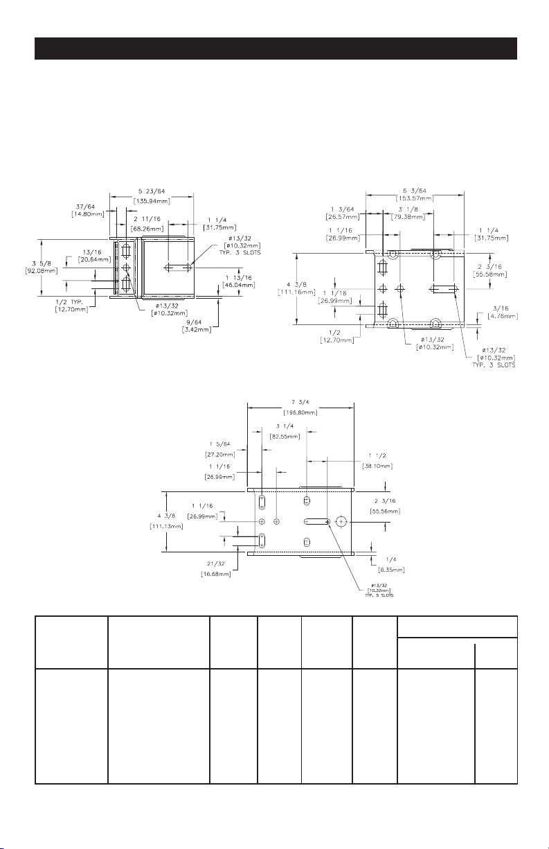
For maximum strength and safety, (and
compliance with SAE Standard J1853) this
winch should be mounted with three 3/8" or
M10 bolts, washers, and lock washers.
Select a winch line with breaking strength
at least 1-1/2 times the winch rating and a
hook 1-1/2 times stronger than the line. If
steel cable is selected, the optional reel with
large hub may extend cable life. (The above
combination meets SAE Standard J1853 for
boat trailer winches).
Attach cable or rope by either method
described in sketch. If nylon strap is used, it
should have a loop sewn in one end and be
attached using a 3/8" x 3" long bolt and locknut. Use a locknut, not a nut and
lock washer. Insert bolt through slots in both reel side plates so that nut is on
gear side. Tighten only until snug with bolt in bottom of slot next to reel
hub.
To mount the winch, the top cover will need to be removed from the
winch. To install cable or strap, the top cover and sides will need
to be removed. See winch cover removal and assembly section for
instructions.
WINCH MOUNTING AND
CABLE ATTACHMENT
CABLE ATTACHMENT METHODS
(IF CABLE IS USED)
3/8" or M10

HANDLE AND NUT MUST BE TIGHTENED AGAINST DRIVE SHAFT
BEFORE OPERATING WINCH. Wind line on winch reel by turning winch han-
dle in clockwise direction with ratchet lever in up position. The ratchet should
produce a loud, sharp clicking noise. Make sure that ratchet lever is in up posi-
tion and holding load before winch handle is released. To unwind or reel out
line, securely grip winch handle and apply force in clockwise direction so that
ratchet lever can easily be moved to down position. Carefully turn handle in
counterclockwise direction. Do not lose control.
The winch can be converted to wind line on
to the underside of the reel. To do this,
carefully examine ratchet assembly
and remove it from winch. Do not
lose small parts. Turn the lever
over and reassemble. Do not
over tighten bolt. Check
operation to insure the
ratchet lever rotates
fully without binding.
OPERATING INSTRUCTIONS
DLx1200, DLx1500 & DLx1900
DLx1200FC - 15 Ft. Strap - 29°
DLx1500FC - 20 Ft. Strap - 25°
DLx1900FC - 20 Ft. Strap - 26°
DLx2300FC - 25 Ft. Strap - 24°
DLx2600FC - 25 Ft. Strap - 26°
MAXIMUM STRAP ANGLE
CAUTION: Exceeding the maximum
strap angle could result in damage to
winch cover.
To Unwind
Ratchet Lever
Up
Down
MAX ANGLE
To Wind
Winch Handle

HANDLE AND NUT MUST BE TIGHTENED AGAINST DRIVE SHAFT BEFORE
OPERATING WINCH. Wind line on winch reel by turning winch handle in count-
er-clockwise direction with ratchet lever in down position. The ratchet should
produce a loud, sharp clicking noise. Make sure that ratchet
lever is in down position and holding load before
winch handle is released. To unwind or reel out
line, securely grip winch handle and
apply force in counter-clockwise
direction so that ratchet lever can
easily be moved to up position.
Carefully turn handle in clock-
wise direction. Do not lose
control. The winch can be
converted to wind line
on to the underside of
the reel. To do this,
carefully examine ratchet
assembly and remove it from winch. Do not lose small parts. Turn the lever over
and reassemble. Do not over tighten bolt. Check operation to insure the ratchet
lever rotates fully without binding.
OPERATING INSTRUCTIONS
DLx2300
Attach winch handle securely to primary drive shaft (upper or low speed shaft).
Make sure that handle clip engages with groove in drive shaft. Wind line on
winch reel by turning winch handle in counterclockwise
direction with ratchet lever in "down" position. The
ratchet should produce a loud, sharp, clicking noise.
Make sure that ratchet lever is in "down"
position and holding load before winch
handle is released. To unwind or reel
out line, securely grip winch handle
and apply force in counterclockwise
direction so that ratchet lever
can easily be moved to "up"
position. Carefully turn handle
in clockwise direction. Do not
lose control. If handle is
attached to intermediate
(lower or high speed) shaft,
operate as described above,
reversing clockwise and counterclockwise. The winch can be converted to wind
line on to the underside of the reel. To do this, carefully examine ratchet assem-
bly and remove it from winch. Do not lose small parts. Turn the lever over and
reassembly. Do not over tighten bolt. Check operation to insure the ratchet lever
rotates fully without binding.
OPERATING INSTRUCTIONS
DLx2600
NOT FOR THE MOVEMENT OF HUMAN BEINGS
Up
To Wind
Down
Ratchet Lever
Up
Winch Handle
To Wind
Ratchet
Lever
Winch Handle
To Unwind
To Unwind
Down
This winch has been fully lubricated at the factory; but, for continued smooth
performance and increased life, occasional greasing of gears and reel shaft and
an occasional drop of oil on drive shaft bearings are recommended.
Keep winch in good working order. Damaged or severely-worn parts create
unnecessary dangers and could result in personal injury or property damage.
WINCH MAINTENANCE
Model Rated Drum Gear Handle Max
Capacity Hub Ratio Length Mech.
Dia. Adv.
DLx1200 1200 lb/544 kg 7/8" 4.4:1 7" 56 7/32" x 56' 31'
DLx1500 1500 lb/680 kg 7/8" 4.4:1 9-1/2" 74 1/4" x 40' 31'
DLx1900 1900 lb/862 kg 1-1/8" 5.4:1 9-1/2" 73 9/32" x 49' 38'
DLx2300 2300 lb/1043 kg 1-1/8" 7.2:1 9-1/2" 95 5/16" x 39' 38'
DLx2600 2600 lb/1179 kg 1-1/8" 17.3:1 9-1/2" 226 5/16" x 47' 38'
/5.4:1
Maximum Drum Capacity
Cable Strap
DLx1200 & DLx1500 DLx1900 & DLx2300
DLx2600

The cover comes off the winch in three pieces. To remove the top cover, loosen
and remove the top phillips screws in the front of the cover with a screwdriver.
Pull up on the front of the top cover and rotate the top away from the winch.
Once the locking tabs are disengaged from the sides, pull the cover straight
back to remove.
To remove the cover sides, use a 9/64 hex key to remove the two socket head
screws in the bottom front and back on the winch side. Once the screws are
removed, pull the cover sides away from the winch to remove.
To reassemble the winch cover, slide the two sides into place around the winch.
Use a 9/64 hex key to install the two socket head screws.
CAUTION: Tighten cover screws by hand only. Over-tightening could
make top cover difficult to install or damage winch cover.
With the sides in place and bolts installed, place the tabs on the back of the top
cover around the bolt on the back of the winch. Rotate the top cover back onto
the winch and press on the middle of the top until the locking tabs snap into
the cover sides. Install the phillips screws in the front of the cover and tighten.
WINCH COVER REMOVAL
AND ASSEMBLY
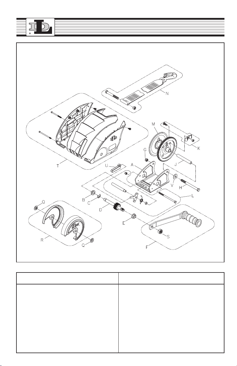
DLx1200 & DLx1500
Ref. Description Part. No.
A Base - DLx1200 406196
A Base - DLx1500 406195
B Bushing 204006
C Retaining Ring 205012
D Drive Shaft 304722
E Bushing 204007
F DLx1200 Handle 7" - Black 5703848
F DLx1500 Handle 9-1/2" - Black 5703855
G Locknut 205270
H Reel Bolt 203161
J Reel Spacer 204807
K Rope Clamp Kit (Opt.) 5243506
Ref. Description Part. No.
L Ratchet Kit 5704556
M Reel - DLx1200 304723-PL
M Reel - DLx1500 306278
N Strap, 20 ft. 5242607
Q Spacer Washer 404916
R Reel Cover Kit 5170030
S Nut 205015
T Full Cover Kit - DLx1200 5170055
T Full Cover Kit - DLX1500 5170295
U Ratchet Pawl Cover 206766
V Washer 205044
To order replacement parts:
Dutton-Lainson Company
www.dlco.com
Tel: 800-569-6577
Fax: 402-460-4612
email: DLsales@dutton-lainson.com
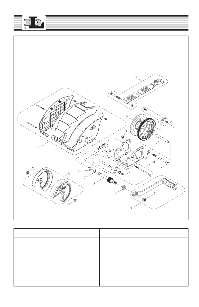
DLx1900
To order replacement parts:
Dutton-Lainson Company
www.dlco.com
Tel: 800-569-6577
Fax: 402-460-4612
email: DLsales@dutton-lainson.com
Ref. Description Part. No.
A Base 406191
B Bushing 204009
C Retaining Ring 205116
D Drive Shaft 304731
F Handle 9-1/2" Black 5703863
H Locknut 205270
J Reel Bolt 204804
K Spacer 204808
L Rope Clamp Kit (Opt.) 5243506
M Ratchet Kit 5704754
Ref. Description Part. No.
N Reel 304779-PL
N Large Hub Reel 306124
P Strap, 20 Ft. 5242409
Q Spacer Washer 404916
R Gear Cover Kit 5170451
T Nut 204809
U Full Cover Kit 5170477
V Ratchet Pawl Cover 206766
W Washer 205044

DLx2300
To order replacement parts:
Dutton-Lainson Company
www.dlco.com
Tel: 800-569-6577
Fax: 402-460-4612
email: DLsales@dutton-lainson.com
Ref. Description Part. No.
A Base - DLx2300 406192
B Bushing 204009
C Retaining Ring 205116
D Primary Shaft 306258
E Bushing 204012
F Handle 9-1/2" - Black 5703863
G Intermediate Shaft 306259
H Locknut 205270
J Reel Bolt 205335
K Reel Spacer 204808
L Rope Clamp Kit (Opt.) 5243506
Ref. Description Part. No.
M Ratchet Kit 5704754
N Reel 304779-PL
N Large Hub Reel 306124
P Strap, 25 Ft. 5242482
Q Spacer Washer 404916
R Gear Cover Kit 5170451
S Nut 204809
U Full Cover Kit 5170683
V Ratchet Pawl Cover 206766
W Washer 205044
Andere Handbücher für DLx1200
1
Dieses Handbuch passt für folgende Modelle
8
Inhaltsverzeichnis
Andere Dutton-Lainson Winde Handbücher

Dutton-Lainson
Dutton-Lainson B1200B Bedienungsanleitung

Dutton-Lainson
Dutton-Lainson Strongarm TW4000 Bedienungsanleitung

Dutton-Lainson
Dutton-Lainson DLx1200 Bedienungsanleitung

Dutton-Lainson
Dutton-Lainson DLB350A Programmierhandbuch

Dutton-Lainson
Dutton-Lainson DL600A Bedienungsanleitung

Dutton-Lainson
Dutton-Lainson B1200G Bedienungsanleitung

Dutton-Lainson
Dutton-Lainson DLx1500FC Bedienungsanleitung

Dutton-Lainson
Dutton-Lainson DL1402A Bedienungsanleitung

Dutton-Lainson
Dutton-Lainson DL400 Bedienungsanleitung

Dutton-Lainson
Dutton-Lainson DL1602A Bedienungsanleitung


