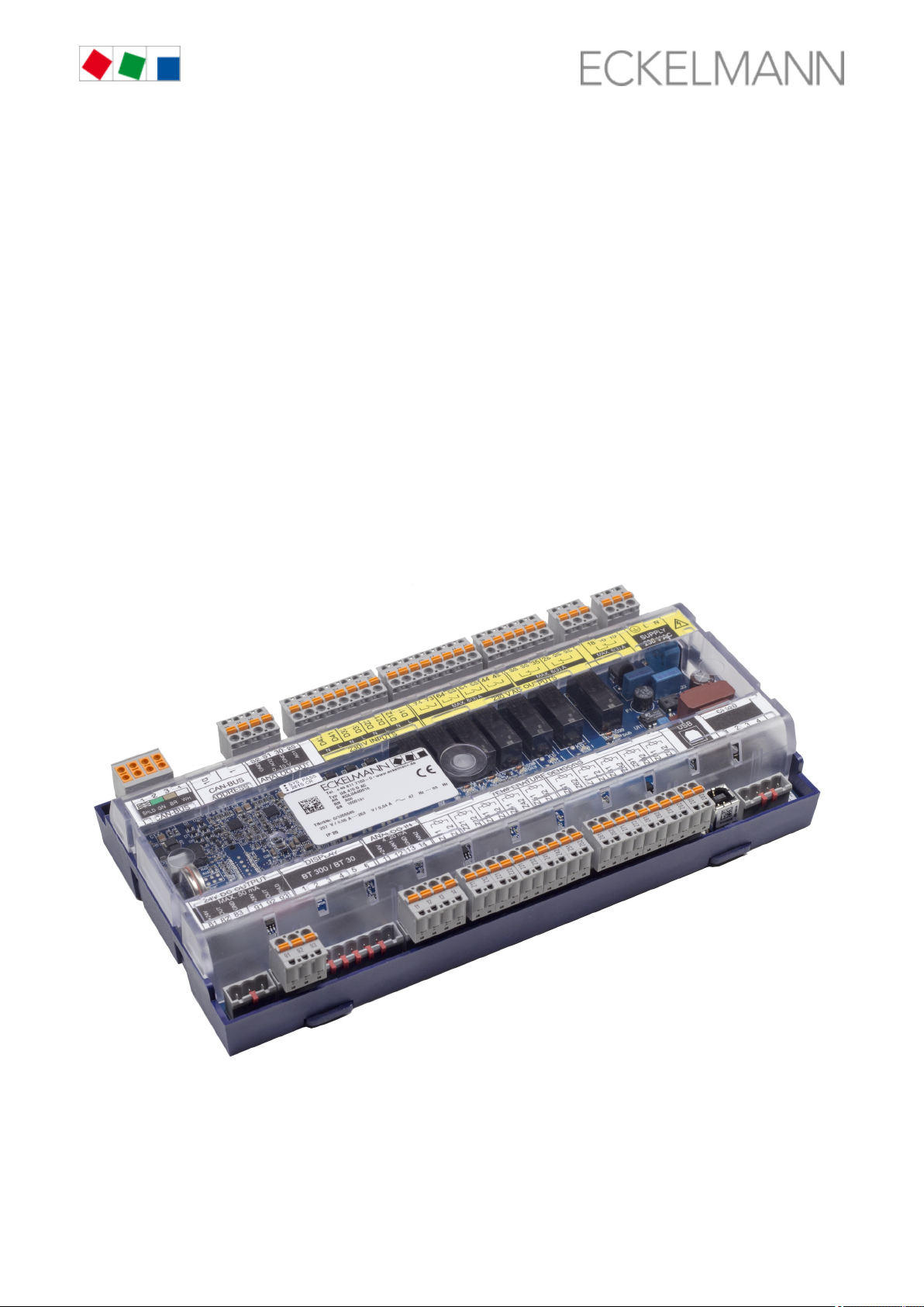
ECKELMANN UA 412 S Bedienungsanleitung

Operating instruction
Case Controller UA 412 S / UA 413 S
Case Controller UA 412 S / UA 413 S - Version V1.16
Version V1.16

KGL Operating Manual – UA 412 S 2019-01-14 /2 122
Eckelmann AG
Business Unit Refrigeration and Building Automation
Berliner Straße 161
65205 Wiesbaden, Germany
Tel.: +49 611 7103-700
Fax: +49 611 7103-133
E-Mail: [email protected]
Internet: www.eckelmann.de
Board of Management:
Dipl.-Ing. Peter Frankenbach, Spokesman,
Dipl.-Wirtsch.-Ing. Philipp Eckelmann, Dr.-Ing. Marco Münchhof, Dr.-Ing. Frank Uhlemann
Chairman of the Supervisory Board: Hubertus G. Krossa
Deputy Chairman of the Supervisory Board: Dr.-Ing. Gerd Eckelmann
Registration court / registration number
District court Wiesbaden, HRB 12636
Before commissioning and use, please check that this is the latest version of the document. With the
publication of a new version of the documentation, all previous versions lose their validity.
Errors and technical modifications are expressly reserved.
The current operating manual and information such as data sheets, more detailed documentation and FAQs
are available for you on-line in E°EDP (Eckelmann ° Electronic Documentation Platform) at
www.eckelmann.de/elds
You reach all relevant documents for this component directly using the QR code:
Information on safety and connection instructions are described in detail in chapter ”Industrial safety notes”.
All rights to any use whatever, utilisation, further development, forwarding and creation of copies remain with
the Eckelmann AG company.
In particular, neither the contract partners of Eckelmann AG nor other users have the right to distribute or
market the IT programs/program parts or modified or edited versions without express written permission. To
some extent, names of products/goods or designations are protected for the respective manufacturer
(registered trademarks etc.); in any case, no guarantee is assumed for their free availability/permission to use
them. The information provided in the description is given independently of any existing patent protection or
other third-party rights.

KGL Operating Manual – UA 412 S 2019-01-14 /3 122
Table of Contents
1 Conventions . . . . . . . . . . . . . . . . . . . . . . . . . . . . . . . . . . . . . . . . . . . . . . . . . . . . . . . . . . . . . . . . . . . . . . . . . . 7
1.1 Explanation of 'Safety Instructions and Hazard Warnings' . . . . . . . . . . . . . . . . . . . . . . . . . . . . . . . . . . . . 7
1.2 Explanation of 'General Note' . . . . . . . . . . . . . . . . . . . . . . . . . . . . . . . . . . . . . . . . . . . . . . . . . . . . . . . . . . 7
1.3 Warning Signs and Symbols Used . . . . . . . . . . . . . . . . . . . . . . . . . . . . . . . . . . . . . . . . . . . . . . . . . . . . . . 7
2 Safety Information . . . . . . . . . . . . . . . . . . . . . . . . . . . . . . . . . . . . . . . . . . . . . . . . . . . . . . . . . . . . . . . . . . . . . 9
2.1 Exclusion of liability for non-observance . . . . . . . . . . . . . . . . . . . . . . . . . . . . . . . . . . . . . . . . . . . . . . . . . 10
2.2 Requirements for the personnel . . . . . . . . . . . . . . . . . . . . . . . . . . . . . . . . . . . . . . . . . . . . . . . . . . . . . . . 10
2.3 Intended Use . . . . . . . . . . . . . . . . . . . . . . . . . . . . . . . . . . . . . . . . . . . . . . . . . . . . . . . . . . . . . . . . . . . . . . 11
2.4 Five safety rules according to BGV A3 . . . . . . . . . . . . . . . . . . . . . . . . . . . . . . . . . . . . . . . . . . . . . . . . . . 11
2.5 Electrostatic sensitive components and control components (ESD) . . . . . . . . . . . . . . . . . . . . . . . . . . . . 11
2.5.1 ESD - guidelines for handling . . . . . . . . . . . . . . . . . . . . . . . . . . . . . . . . . . . . . . . . . . . . . . . . . . . . 12
2.6 Abbreviations used . . . . . . . . . . . . . . . . . . . . . . . . . . . . . . . . . . . . . . . . . . . . . . . . . . . . . . . . . . . . . . . . . 12
3 System design UA 412 S . . . . . . . . . . . . . . . . . . . . . . . . . . . . . . . . . . . . . . . . . . . . . . . . . . . . . . . . . . . . . . . 13
3.1 Application . . . . . . . . . . . . . . . . . . . . . . . . . . . . . . . . . . . . . . . . . . . . . . . . . . . . . . . . . . . . . . . . . . . . . . . . 13
3.2 Hardware . . . . . . . . . . . . . . . . . . . . . . . . . . . . . . . . . . . . . . . . . . . . . . . . . . . . . . . . . . . . . . . . . . . . . . . . . 13
4 Applications UA 412 S . . . . . . . . . . . . . . . . . . . . . . . . . . . . . . . . . . . . . . . . . . . . . . . . . . . . . . . . . . . . . . . . . 16
4.1 Controller types . . . . . . . . . . . . . . . . . . . . . . . . . . . . . . . . . . . . . . . . . . . . . . . . . . . . . . . . . . . . . . . . . . . . 16
4.2 Versions . . . . . . . . . . . . . . . . . . . . . . . . . . . . . . . . . . . . . . . . . . . . . . . . . . . . . . . . . . . . . . . . . . . . . . . . . 17
4.3 Firmware Update . . . . . . . . . . . . . . . . . . . . . . . . . . . . . . . . . . . . . . . . . . . . . . . . . . . . . . . . . . . . . . . . . . . 17
5 Function UA 412 S . . . . . . . . . . . . . . . . . . . . . . . . . . . . . . . . . . . . . . . . . . . . . . . . . . . . . . . . . . . . . . . . . . . . 19
5.1 Starting characteristics . . . . . . . . . . . . . . . . . . . . . . . . . . . . . . . . . . . . . . . . . . . . . . . . . . . . . . . . . . . . . . 19
5.1.1 First start- reset controller to factory settings . . . . . . . . . . . . . . . . . . . . . . . . . . . . . . . . . . . . . . . . 19
5.1.2 Restart - restart of the controller . . . . . . . . . . . . . . . . . . . . . . . . . . . . . . . . . . . . . . . . . . . . . . . . . . 19
5.2 Selection of the sensor type. . . . . . . . . . . . . . . . . . . . . . . . . . . . . . . . . . . . . . . . . . . . . . . . . . . . . . . . . . . 19
5.2.1 Necessary and optional sensors . . . . . . . . . . . . . . . . . . . . . . . . . . . . . . . . . . . . . . . . . . . . . . . . . . 20
5.3 Description of the controller function . . . . . . . . . . . . . . . . . . . . . . . . . . . . . . . . . . . . . . . . . . . . . . . . . . . . 21
5.4 Safety chain . . . . . . . . . . . . . . . . . . . . . . . . . . . . . . . . . . . . . . . . . . . . . . . . . . . . . . . . . . . . . . . . . . . . . . 22
5.5 Cooling . . . . . . . . . . . . . . . . . . . . . . . . . . . . . . . . . . . . . . . . . . . . . . . . . . . . . . . . . . . . . . . . . . . . . . . . . . 22
5.5.1 Compressor enable according to supply air and return air . . . . . . . . . . . . . . . . . . . . . . . . . . . . . . 22
5.5.2 Compressor control . . . . . . . . . . . . . . . . . . . . . . . . . . . . . . . . . . . . . . . . . . . . . . . . . . . . . . . . . . . . 23
5.5.2.1 Controller type SPIR410 . . . . . . . . . . . . . . . . . . . . . . . . . . . . . . . . . . . . . . . . . . . . . . . . . . . . . 25
5.5.2.2 Controller type SPIR290 . . . . . . . . . . . . . . . . . . . . . . . . . . . . . . . . . . . . . . . . . . . . . . . . . . . . . 26
5.5.3 Compressor end temperature . . . . . . . . . . . . . . . . . . . . . . . . . . . . . . . . . . . . . . . . . . . . . . . . . . . . 27
5.5.4 Continuous run monitoring of the regulation . . . . . . . . . . . . . . . . . . . . . . . . . . . . . . . . . . . . . . . . . 27
5.5.5 Minimum running and standstill times . . . . . . . . . . . . . . . . . . . . . . . . . . . . . . . . . . . . . . . . . . . . . . 28
5.5.6 Emergency operation . . . . . . . . . . . . . . . . . . . . . . . . . . . . . . . . . . . . . . . . . . . . . . . . . . . . . . . . . . 28
5.6 Defrost . . . . . . . . . . . . . . . . . . . . . . . . . . . . . . . . . . . . . . . . . . . . . . . . . . . . . . . . . . . . . . . . . . . . . . . . . . . 28
5.6.1 General notes for defrost . . . . . . . . . . . . . . . . . . . . . . . . . . . . . . . . . . . . . . . . . . . . . . . . . . . . . . . 28
5.6.2 Master-slave mode for the synchronisation of the defrost termination . . . . . . . . . . . . . . . . . . . . . 31
5.6.2.1 Master-slave mode for the synchronisation of multiple controllers . . . . . . . . . . . . . . . . . . . . . 31

KGL Operating Manual – UA 412 S 2019-01-14 /4 122
5.6.2.1 Master-slave mode for the synchronisation of multiple controllers . . . . . . . . . . . . . . . . . . . . . 31
5.6.2.2 Necessary settings for the master / slave mode . . . . . . . . . . . . . . . . . . . . . . . . . . . . . . . . . . . 31
5.6.2.3 Special features and limitations . . . . . . . . . . . . . . . . . . . . . . . . . . . . . . . . . . . . . . . . . . . . . . . . 32
5.7 Fan control . . . . . . . . . . . . . . . . . . . . . . . . . . . . . . . . . . . . . . . . . . . . . . . . . . . . . . . . . . . . . . . . . . . . . . . 34
5.8 Frame heater . . . . . . . . . . . . . . . . . . . . . . . . . . . . . . . . . . . . . . . . . . . . . . . . . . . . . . . . . . . . . . . . . . . . . . 34
5.9 Manual shutdown . . . . . . . . . . . . . . . . . . . . . . . . . . . . . . . . . . . . . . . . . . . . . . . . . . . . . . . . . . . . . . . . . . 35
5.10 Toggle setpoint (day / night operation) . . . . . . . . . . . . . . . . . . . . . . . . . . . . . . . . . . . . . . . . . . . . . . . . . 35
5.11 Lighting control . . . . . . . . . . . . . . . . . . . . . . . . . . . . . . . . . . . . . . . . . . . . . . . . . . . . . . . . . . . . . . . . . . . 35
5.12 Emergency power operation . . . . . . . . . . . . . . . . . . . . . . . . . . . . . . . . . . . . . . . . . . . . . . . . . . . . . . . . . 36
5.13 BT 30 temperature display . . . . . . . . . . . . . . . . . . . . . . . . . . . . . . . . . . . . . . . . . . . . . . . . . . . . . . . . . . 37
5.14 Recording of messages and alarms . . . . . . . . . . . . . . . . . . . . . . . . . . . . . . . . . . . . . . . . . . . . . . . . . . . 38
6 UA 412 S installation and start-up . . . . . . . . . . . . . . . . . . . . . . . . . . . . . . . . . . . . . . . . . . . . . . . . . . . . . . . . 39
6.1 Installation . . . . . . . . . . . . . . . . . . . . . . . . . . . . . . . . . . . . . . . . . . . . . . . . . . . . . . . . . . . . . . . . . . . . . . . . 39
6.1.1 Case controller for DIN rail mounting . . . . . . . . . . . . . . . . . . . . . . . . . . . . . . . . . . . . . . . . . . . . . . 39
6.1.1.1 Mounting on the DIN rail . . . . . . . . . . . . . . . . . . . . . . . . . . . . . . . . . . . . . . . . . . . . . . . . . . . . . 40
6.1.1.2 Removal from the DIN rail . . . . . . . . . . . . . . . . . . . . . . . . . . . . . . . . . . . . . . . . . . . . . . . . . . . . 41
6.1.2 Handling of the spring terminals . . . . . . . . . . . . . . . . . . . . . . . . . . . . . . . . . . . . . . . . . . . . . . . . . . 42
6.2 Basic settings . . . . . . . . . . . . . . . . . . . . . . . . . . . . . . . . . . . . . . . . . . . . . . . . . . . . . . . . . . . . . . . . . . . . . 43
6.3 Setting the CAN bus address . . . . . . . . . . . . . . . . . . . . . . . . . . . . . . . . . . . . . . . . . . . . . . . . . . . . . . . . . 44
6.4 Setting of the controller type and master/slave mode . . . . . . . . . . . . . . . . . . . . . . . . . . . . . . . . . . . . . . . 45
6.5 Power supply . . . . . . . . . . . . . . . . . . . . . . . . . . . . . . . . . . . . . . . . . . . . . . . . . . . . . . . . . . . . . . . . . . . . . . 47
6.5.1 Status LEDs . . . . . . . . . . . . . . . . . . . . . . . . . . . . . . . . . . . . . . . . . . . . . . . . . . . . . . . . . . . . . . . . . 47
6.6 Basic configuration of the controller . . . . . . . . . . . . . . . . . . . . . . . . . . . . . . . . . . . . . . . . . . . . . . . . . . . . 48
6.7 Naming the controller . . . . . . . . . . . . . . . . . . . . . . . . . . . . . . . . . . . . . . . . . . . . . . . . . . . . . . . . . . . . . . . 51
6.8 Battery replacement . . . . . . . . . . . . . . . . . . . . . . . . . . . . . . . . . . . . . . . . . . . . . . . . . . . . . . . . . . . . . . . . 52
6.9 Firmware Update . . . . . . . . . . . . . . . . . . . . . . . . . . . . . . . . . . . . . . . . . . . . . . . . . . . . . . . . . . . . . . . . . . . 54
6.9.1 Requirements for firmware update . . . . . . . . . . . . . . . . . . . . . . . . . . . . . . . . . . . . . . . . . . . . . . . . 54
6.9.2 Installing firmware update . . . . . . . . . . . . . . . . . . . . . . . . . . . . . . . . . . . . . . . . . . . . . . . . . . . . . . . 56
6.9.2.1 Update for controller with 9-pole DIP switch . . . . . . . . . . . . . . . . . . . . . . . . . . . . . . . . . . . . . . 56
6.9.2.2 Update for controller with 8-pole DIP switch . . . . . . . . . . . . . . . . . . . . . . . . . . . . . . . . . . . . . . 59
6.9.3 Rectification of driver problems . . . . . . . . . . . . . . . . . . . . . . . . . . . . . . . . . . . . . . . . . . . . . . . . . . . 63
7 UA 412 S connection and terminal assignment . . . . . . . . . . . . . . . . . . . . . . . . . . . . . . . . . . . . . . . . . . . . . . 64
7.1 Terminal diagram . . . . . . . . . . . . . . . . . . . . . . . . . . . . . . . . . . . . . . . . . . . . . . . . . . . . . . . . . . . . . . . . . . 64
7.2 Terminal assignment of the 230 V AC power supply . . . . . . . . . . . . . . . . . . . . . . . . . . . . . . . . . . . . . . . 64
7.3 Terminal assignment of the 230 V AC relay outputs . . . . . . . . . . . . . . . . . . . . . . . . . . . . . . . . . . . . . . . . 65
7.4 Assignment of the 230 V AC digital inputs . . . . . . . . . . . . . . . . . . . . . . . . . . . . . . . . . . . . . . . . . . . . . . . 66
7.5 Assignment of the 0..10 V analogue outputs DEF . . . . . . . . . . . . . . . . . . . . . . . . . . . . . . . . . . . . . . . . . 67
7.6 Terminal assignment of the CAN bus terminals . . . . . . . . . . . . . . . . . . . . . . . . . . . . . . . . . . . . . . . . . . . 68
7.7 Terminal assignment of the 24 V DC transistor outputs . . . . . . . . . . . . . . . . . . . . . . . . . . . . . . . . . . . . . 69
7.7.1 Function of the relay and transistor outputs . . . . . . . . . . . . . . . . . . . . . . . . . . . . . . . . . . . . . . . . . 70
7.8 Assignment of the DISPLAY interface . . . . . . . . . . . . . . . . . . . . . . . . . . . . . . . . . . . . . . . . . . . . . . . . . . 71
7.9 Assignment of the 4..20 mA analogue inputs . . . . . . . . . . . . . . . . . . . . . . . . . . . . . . . . . . . . . . . . . . . . . 71
7.10 Terminal assignment of the analogue inputs for temperature sensors . . . . . . . . . . . . . . . . . . . . . . . . . 72

KGL Operating Manual – UA 412 S 2019-01-14 /5 122
7.10 Terminal assignment of the analogue inputs for temperature sensors . . . . . . . . . . . . . . . . . . . . . . . . . 72
7.10.1 Explanation for the sensor designation . . . . . . . . . . . . . . . . . . . . . . . . . . . . . . . . . . . . . . . . . . . . 73
7.11 Assignment of the USB port . . . . . . . . . . . . . . . . . . . . . . . . . . . . . . . . . . . . . . . . . . . . . . . . . . . . . . . . . 74
7.12 Wiring of the master-slave function for defrost synchronisation . . . . . . . . . . . . . . . . . . . . . . . . . . . . . . 74
8 Operation UA 412 S . . . . . . . . . . . . . . . . . . . . . . . . . . . . . . . . . . . . . . . . . . . . . . . . . . . . . . . . . . . . . . . . . . . 76
8.1 Operation possibilities . . . . . . . . . . . . . . . . . . . . . . . . . . . . . . . . . . . . . . . . . . . . . . . . . . . . . . . . . . . . . . . 76
8.2 Local operation with a BT 300 x operator interface: . . . . . . . . . . . . . . . . . . . . . . . . . . . . . . . . . . . . . . . . 76
8.2.1 Locking of the setpoint change . . . . . . . . . . . . . . . . . . . . . . . . . . . . . . . . . . . . . . . . . . . . . . . . . . . 77
8.3 Remote control via the terminal . . . . . . . . . . . . . . . . . . . . . . . . . . . . . . . . . . . . . . . . . . . . . . . . . . . . . . . 78
8.3.1 Menus and operating screens . . . . . . . . . . . . . . . . . . . . . . . . . . . . . . . . . . . . . . . . . . . . . . . . . . . . 79
8.3.2 Call controller menu using remote operation, page 115 . . . . . . . . . . . . . . . . . . . . . . . . . . . . . . . . 82
8.3.2.1 CI 4x00 System Centre . . . . . . . . . . . . . . . . . . . . . . . . . . . . . . . . . . . . . . . . . . . . . . . . . . . . . . 82
8.3.2.2 CI 3x00 store computer / AL 300 operator terminal . . . . . . . . . . . . . . . . . . . . . . . . . . . . . . . . . 82
8.3.3 Cancelling entry block . . . . . . . . . . . . . . . . . . . . . . . . . . . . . . . . . . . . . . . . . . . . . . . . . . . . . . . . . . 83
8.3.3.1 CI 4x00 System Centre . . . . . . . . . . . . . . . . . . . . . . . . . . . . . . . . . . . . . . . . . . . . . . . . . . . . . . 83
8.3.3.2 CI 3x00 store computer / AL 300 operator terminal . . . . . . . . . . . . . . . . . . . . . . . . . . . . . . . . . 84
8.3.4 Activating service mode . . . . . . . . . . . . . . . . . . . . . . . . . . . . . . . . . . . . . . . . . . . . . . . . . . . . . . . . 84
8.3.4.1 CI 4x00 System Centre . . . . . . . . . . . . . . . . . . . . . . . . . . . . . . . . . . . . . . . . . . . . . . . . . . . . . . 84
8.3.4.2 Store computer CI 3x00 . . . . . . . . . . . . . . . . . . . . . . . . . . . . . . . . . . . . . . . . . . . . . . . . . . . . . . 85
9 Menu structure . . . . . . . . . . . . . . . . . . . . . . . . . . . . . . . . . . . . . . . . . . . . . . . . . . . . . . . . . . . . . . . . . . . . . . . 86
9.1 Controller type SPIR410 - Menu tree . . . . . . . . . . . . . . . . . . . . . . . . . . . . . . . . . . . . . . . . . . . . . . . . . . . 86
9.1.1 Main menu . . . . . . . . . . . . . . . . . . . . . . . . . . . . . . . . . . . . . . . . . . . . . . . . . . . . . . . . . . . . . . . . . . 87
9.1.2 Menu 1 Actual values . . . . . . . . . . . . . . . . . . . . . . . . . . . . . . . . . . . . . . . . . . . . . . . . . . . . . . . . . . 87
9.1.3 Menu 2 Setpoints . . . . . . . . . . . . . . . . . . . . . . . . . . . . . . . . . . . . . . . . . . . . . . . . . . . . . . . . . . . . . 89
9.1.4 Menu 3 Clock . . . . . . . . . . . . . . . . . . . . . . . . . . . . . . . . . . . . . . . . . . . . . . . . . . . . . . . . . . . . . . . . 91
9.1.5 Menu 4 Messages . . . . . . . . . . . . . . . . . . . . . . . . . . . . . . . . . . . . . . . . . . . . . . . . . . . . . . . . . . . . . 93
9.1.6 Menu 5 Archive . . . . . . . . . . . . . . . . . . . . . . . . . . . . . . . . . . . . . . . . . . . . . . . . . . . . . . . . . . . . . . . 93
9.1.7 Menu 6 Configuration . . . . . . . . . . . . . . . . . . . . . . . . . . . . . . . . . . . . . . . . . . . . . . . . . . . . . . . . . . 94
9.2 Controller type SPIR290 - Menu tree . . . . . . . . . . . . . . . . . . . . . . . . . . . . . . . . . . . . . . . . . . . . . . . . . . . 98
9.2.1 Main menu . . . . . . . . . . . . . . . . . . . . . . . . . . . . . . . . . . . . . . . . . . . . . . . . . . . . . . . . . . . . . . . . . 100
9.2.2 Menu 1 Actual values . . . . . . . . . . . . . . . . . . . . . . . . . . . . . . . . . . . . . . . . . . . . . . . . . . . . . . . . . 100
9.2.3 Menu 2 Setpoints . . . . . . . . . . . . . . . . . . . . . . . . . . . . . . . . . . . . . . . . . . . . . . . . . . . . . . . . . . . . 101
9.2.4 Menu 3 Clock . . . . . . . . . . . . . . . . . . . . . . . . . . . . . . . . . . . . . . . . . . . . . . . . . . . . . . . . . . . . . . . 104
9.2.5 Menu 4 Messages . . . . . . . . . . . . . . . . . . . . . . . . . . . . . . . . . . . . . . . . . . . . . . . . . . . . . . . . . . . 106
9.2.6 Menu 5 Archive . . . . . . . . . . . . . . . . . . . . . . . . . . . . . . . . . . . . . . . . . . . . . . . . . . . . . . . . . . . . . 106
9.2.7 Menu 6 Configuration . . . . . . . . . . . . . . . . . . . . . . . . . . . . . . . . . . . . . . . . . . . . . . . . . . . . . . . . . 107
10 Decommissioning and disposal . . . . . . . . . . . . . . . . . . . . . . . . . . . . . . . . . . . . . . . . . . . . . . . . . . . . . . . . 112
10.1 Decommissioning / Dismantling . . . . . . . . . . . . . . . . . . . . . . . . . . . . . . . . . . . . . . . . . . . . . . . . . . . . . 112
10.2 Disposal . . . . . . . . . . . . . . . . . . . . . . . . . . . . . . . . . . . . . . . . . . . . . . . . . . . . . . . . . . . . . . . . . . . . . . . 112
11 Alarms and messages UA 412 S . . . . . . . . . . . . . . . . . . . . . . . . . . . . . . . . . . . . . . . . . . . . . . . . . . . . . . . 113
11.1 Alarm signaling and monitoring . . . . . . . . . . . . . . . . . . . . . . . . . . . . . . . . . . . . . . . . . . . . . . . . . . . . . . 114
11.1.1 Alarm for overtemperature or low temperature . . . . . . . . . . . . . . . . . . . . . . . . . . . . . . . . . . . . . 114
11.1.2 Alarm in the absence of a defrost . . . . . . . . . . . . . . . . . . . . . . . . . . . . . . . . . . . . . . . . . . . . . . . 114
11.1.3 Alarm due to sensor fault . . . . . . . . . . . . . . . . . . . . . . . . . . . . . . . . . . . . . . . . . . . . . . . . . . . . . 115

11.1.4 Alarm suppression of the sensor fault alarm during a defrost . . . . . . . . . . . . . . . . . . . . . . . . . 115
11.1.5 Alarm due to hardware problems . . . . . . . . . . . . . . . . . . . . . . . . . . . . . . . . . . . . . . . . . . . . . . . 115
11.1.6 Restart . . . . . . . . . . . . . . . . . . . . . . . . . . . . . . . . . . . . . . . . . . . . . . . . . . . . . . . . . . . . . . . . . . . 115

KGL Operating Manual – UA 412 S 2019-01-14 /6 122
11.1.6 Restart . . . . . . . . . . . . . . . . . . . . . . . . . . . . . . . . . . . . . . . . . . . . . . . . . . . . . . . . . . . . . . . . . . . 115
11.2 Individual allocation of priorities . . . . . . . . . . . . . . . . . . . . . . . . . . . . . . . . . . . . . . . . . . . . . . . . . . . . . 116
11.3 Alarm paths . . . . . . . . . . . . . . . . . . . . . . . . . . . . . . . . . . . . . . . . . . . . . . . . . . . . . . . . . . . . . . . . . . . . . 117
11.4 End of an alarm . . . . . . . . . . . . . . . . . . . . . . . . . . . . . . . . . . . . . . . . . . . . . . . . . . . . . . . . . . . . . . . . . . 117
11.5 Messages . . . . . . . . . . . . . . . . . . . . . . . . . . . . . . . . . . . . . . . . . . . . . . . . . . . . . . . . . . . . . . . . . . . . . . 117
11.5.1 Transient alarms and messages . . . . . . . . . . . . . . . . . . . . . . . . . . . . . . . . . . . . . . . . . . . . . . . . 117
11.5.2 Message list . . . . . . . . . . . . . . . . . . . . . . . . . . . . . . . . . . . . . . . . . . . . . . . . . . . . . . . . . . . . . . . 118
12 Technical Data UA 412 S . . . . . . . . . . . . . . . . . . . . . . . . . . . . . . . . . . . . . . . . . . . . . . . . . . . . . . . . . . . . . 119
12.1 Electrical data . . . . . . . . . . . . . . . . . . . . . . . . . . . . . . . . . . . . . . . . . . . . . . . . . . . . . . . . . . . . . . . . . . . 119
12.2 Mechanical Data UA 412 S . . . . . . . . . . . . . . . . . . . . . . . . . . . . . . . . . . . . . . . . . . . . . . . . . . . . . . . . . 121
12.3 Mechanical data of the temperature sensors L243 / 5K3A1 / Pt1000 . . . . . . . . . . . . . . . . . . . . . . . . . 121
13 Order numbers and accessories of UA 412 S . . . . . . . . . . . . . . . . . . . . . . . . . . . . . . . . . . . . . . . . . . . . . 122
13.1 Case controller . . . . . . . . . . . . . . . . . . . . . . . . . . . . . . . . . . . . . . . . . . . . . . . . . . . . . . . . . . . . . . . . . . 122
13.2 Accessories . . . . . . . . . . . . . . . . . . . . . . . . . . . . . . . . . . . . . . . . . . . . . . . . . . . . . . . . . . . . . . . . . . . . . 122

KGL Operating Manual – UA 412 S 2019-01-14 /7 122
1.
2.
3.
4.
1.
2.
1 Conventions
1.1 Explanation of 'Safety Instructions and Hazard Warnings'
Safety instructions or hazard warnings are composed of four elements:
The pictogram and the text at the side pf the page.
A short, concise description of the danger.
A description of the possible consequences.
A catalogue with measures for avoidance.
For example:
Warning about dangerous electrical voltage! Danger of electric shock! BEFORE connecting and
disconnecting, it must be checked that at the 230 V AC relay outputs!no voltage is present
1.2 Explanation of 'General Note'
A general note consists of two elements:
The pictogram and the "Info" text at the side pf the page, and
the actual note text:
For example:
Further information for the protection rating of the device is contained in the chapter Technical Data
.UA 412 S, page 119
1.3 Warning Signs and Symbols Used
Explanation of the warning signs and symbols used for the safety instructions and hazard warnings in this
documentation:
Attention symbol - general hazard warning
1. Hazard warning
The attention symbol indicates all safety instructions in this operating and service manual that result
in danger to life and limb of persons if not observed. Carefully comply with the work safety
instructions and proceed with particular caution in these cases.
2. Attention
The attention symbol highlights guidelines, regulations, instructions and correct working procedures
that must particularly be observed in order to prevent damage to and destruction of E*LDS
components or any malfunction (for example to prevent damage to goods).
Failure to observe the attention symbol can result in personal injury (in extreme cases serious injuries or
death) and/or damage to property!
Warning Symbol

KGL Operating Manual – UA 412 S 2019-01-14 /8 122
Warning Symbol
1. Warning about dangerous electrical voltage
This work safety s ymbol warns about hazards from dangerous electrical voltage with possible
consequences of serious injuries and death.
Failure to observe this symbol can result in personal injuries (serious personal injuries or death in
extreme cases) and/or in damage to property!
If this symbol is seen, the operating manual must be consulted to find out the type of the potential
HAZARD and the required actions for the avoidance of the HAZARD.
2. Warning about electrostatic sensitive components and control components
This symbol also indicates electrostatic sensitive components and control components.
Note symbol
The note symbol highlights usage tips and other useful information contained in this operating and
service manual.
Battery disposal symbol
Never dispose of this product using the residual waste bin.
Please inform yourself about the local regulations for the separated disposal of electrical and electronic products.
The correct disposal of your old equipment protects the environment and people against possible negative consequences. Further
information for this can be found in the chapter " ".Decommissioning and Disposal, page 112

KGL Operating Manual – UA 412 S 2019-01-14 /9 122
2 Safety Information
The safety regulations, instructions and information described in this chapter must be strictly
observed and complied with. During repairs on the entire E*LDS system, the accident prevention
regulations and general safety regulations must be strictly complied with. Important information
(safety instructions and hazard warnings) are indicated by appropriate symbols (see chapter
). Follow these instructions in order to prevent accidents and danger to life Conventions, page 7
and limb, as well as damage to the E*LDS system.
Warning about dangerous electrical voltage! Danger of electric shock! Beware of external voltage at
the digital inputs and outputs! All device connections/male connectors may only be plugged in,
unplugged and/or wired when .no voltage is present
This operating manual is part of the device. It be kept in the vicinity of the controller as well as for must
future use so that it can be consulted when required. The operating manual must be available for the
operating and maintenance personnel for the avoidance of operating errors, see chapter at any time
.Requirements for the personnel, page 10
For safety reasons, the equipment must not be used for any applications other than described in the
operating manual and only for the intended use, see chapter .Intended Use, page 11
Before using the device, check whether it is suitable for your application with regard to its limit values.
The equipment must be installed in an electrically shielded area within the switch cabinet.
Before connecting the device, it must be checked whether the power supply is suitable for the device.
When using uncoded plug connectors, it is possible to connect them so that there is a danger to life and
limb! If this cannot be ruled out, coded plug connectors must be used .
Specified environmental conditions (e.g. humidity and temperature limits) must be observed and
complied with. Otherwise, malfunctions are possible (see chapter ).Technical Data UA 412 S, page 119
Before switching on the device, check correct wiring of the connections.
The device must never be operated without its case. Before opening the case, the device must be
disconnected from the power supply.
Note the maximum load of the relay contacts (see chapter ).Technical Data UA 412 S, page 119
Contact the supplier in the case of any malfunction.
Note that all supply lines from and to the device, particularly those of the CAN bus must be shielded or
installed with sufficiently large distance from live cables. This prevents faulty measurements and
protects the device against electrical interference via the analogue inputs. Connection in parallel of RC
elements is recommended for applications with critical environment.

KGL Operating Manual – UA 412 S 2019-01-14 /10 122
1.
2.
According to experience, transmission of alarms is not yet functional during putting into service
(no telephone line laid etc.). It is strongly recommended in such cases to monitor the controller
via the CAN bus using a system centre, a store computer or an operator terminal and to
enable transmission of alarms, for example using a GSM modem via a mobile telephone
system. In standalone operation, or as an alternative to monitoring with system centre / store
computer / operator terminal, an available alarm contact on the controller must be used to
realise transmission of alarms via a telephone network.
For fire prevention reasons, a suitable device for shutting down the defrost heating in the
event of excessive temperatures (high temperature circuit breaker) must already be taken into
account during planning of the installation.
For further information about the CAN bus, see the manual “Basics and General Safety and
Connection Notes”.
Work on the electrical system may (according only be performed by authorised specialist personnel
to the definition for specialists in DIN/VDE 0105 and IEC364) and in accordance with the respective
applicable
VDE regulations, local safety regulations
Intended use
Five safety rules according to BGV A3
ESD measures
Operating instructions
2.1 Exclusion of liability for non-observance
This operating manual contains information about the putting into service, function, operation and maintenance
of the controller and the associated components.
A basic requirement for safe and trouble-free operation is .compliance with this operating manual
2.2 Requirements for the personnel
Special technical knowledge is required for planning, programming, installation, putting into service and
maintenance work. This work may only be performed by trained or specially trained personnel. The installation,
putting into service and maintenance personnel must have training which authorises interventions in the
system and the automation system. The planning and programming personnel must be familiar with the safety
concepts of automation technology. Specialist knowledge is required for work on electrical systems. Work on
electrical systems may only be carried out by qualified electricians or persons under their guidance or
supervision. In doing so, the respective applicable regulations (e.g. DIN EN 60204, EN 5017 DIN 8, BGV A3,
VDE 0100/0113) must be observed. The operating personnel must be instructed in handling the system /
machine and the controller and must be familiar with the operating instructions.
Dieses Handbuch passt für folgende Modelle
1
Inhaltsverzeichnis
Andere ECKELMANN Controller Handbücher

ECKELMANN
ECKELMANN UA 400 Bedienungsanleitung

ECKELMANN
ECKELMANN UA 300 D Bedienungsanleitung

ECKELMANN
ECKELMANN UA 410 D Bedienungsanleitung

ECKELMANN
ECKELMANN VS 3000 Bedienungsanleitung

ECKELMANN
ECKELMANN VS 3000 BS Bedienungsanleitung

ECKELMANN
ECKELMANN VS 3010 BS Bedienungsanleitung

ECKELMANN
ECKELMANN WRG 3010 E Bedienungsanleitung

ECKELMANN
ECKELMANN VS 3015 C Bedienungsanleitung

ECKELMANN
ECKELMANN UA 410 L Case Controller Bedienungsanleitung

ECKELMANN
ECKELMANN VS 3015 CT Bedienungsanleitung