
EFD MINAC 25 Twin Bedienungsanleitung

MINAC Systems
Mobile Induction Heating Equipment
USER MANUAL
MINAC 25/40, 50/80
MINAC 25 Twin
Version MCCC 2.2.1
Manufacturer:EFD Induction a.s
P.O. Box 363, N-3701 Skien, Norway
Tel: +47 35506000 Fax: +47 35506010
©No part of this publication may be reproduced in any form without the
express written permission of EFD Induction a.s. EFD Induction a.s
reserves the right to change technical specifications without notice.

MINAC Systems Revision A
USER MANUAL 31 January 2005
63860.doc
© For reproduction rights, see cover page.
Page
i
C O N T E N T S
1INTRODUCTION ..............................................................................................1
2SAFETY INSTRUCTIONS, PRECAUTIONS AND HAZARDS.......................... 2
2.1 General.........................................................................................................2
2.2 Electric Shocks.............................................................................................3
2.3 Heated Objects.............................................................................................3
2.4 Electromagnetic Fields.................................................................................4
3RESTRICTIONS IN USE..................................................................................5
4CONNECTING AND USING THE COIL ...........................................................6
5MAN-MACHINE INTERFACE...........................................................................7
5.1 Display and Keyboard ..................................................................................7
5.1.1 Footer Messages....................................................................................10
5.2 Menus.........................................................................................................12
5.2.1 Activate Menu (menu 2).........................................................................12
5.2.2 PIN Code Menu (menu 26).....................................................................13
5.2.3 Change PIN code Menu (menu 27)........................................................14
5.2.4 Setpoint Menu (menu 3)......................................................................... 14
5.2.5 Timer Menu (menu 7)............................................................................. 15
5.2.6 Sequence Menu (menu 4)......................................................................15
5.2.7 Energy Menu (menu 8)...........................................................................20
5.2.8 Event output menu (menu 30)................................................................21
5.2.9 Display Values (menu 24) ...................................................................... 22
5.2.10 Display All Values (menu 19) .................................................................22
5.2.11 Display Timer/Sequence (menu 23).......................................................22
5.2.12 Display Twin Values (menu 36) (Only Twin units).................................. 22
5.2.13 Status menu F7 (menu 29)..................................................................... 22
6OPERATION...................................................................................................23
6.1 Before Starting............................................................................................ 23
6.2 Start............................................................................................................ 25
6.2.1 Main switch.............................................................................................25
6.2.2 Programming the MMI............................................................................25
6.2.3 Power on................................................................................................26

MINAC Systems Revision A
USER MANUAL 31 January 2005
63860.doc
© For reproduction rights, see cover page.
Page
ii
6.2.4 Alarms during start-up............................................................................28
6.3 Normal Operation.......................................................................................28
6.3.1 Operational Information..........................................................................29
6.3.2 Control Functions...................................................................................29
6.3.3 Output Power .........................................................................................31
6.3.4 Distance to Workpiece............................................................................31
6.4 Normal Stop................................................................................................32
6.5 Emergency Stop......................................................................................... 32
6.6 Restart after Emergency Stop Command...................................................33
6.7 Disturbance of Operation and Corrective Measures...................................34
MINAC Systems Revision A
USER MANUAL 31 January 2005
63860.doc
© For reproduction rights, see cover page.
Page
1
1INTRODUCTION
This manual provides step-by-step operation instructions for the MINAC standard
25/40 and 50/80 systems and MINAC 25 Twin systems. It also contains safety
information and instructions, and some simple corrective measures.
The operation instructions must be read thoroughly before the equipment is used.
Using these instructions, MINAC operators should be able to undertake correct and
safe operation. However, only qualified personnel should carry out general trouble-
shooting and maintenance tasks.
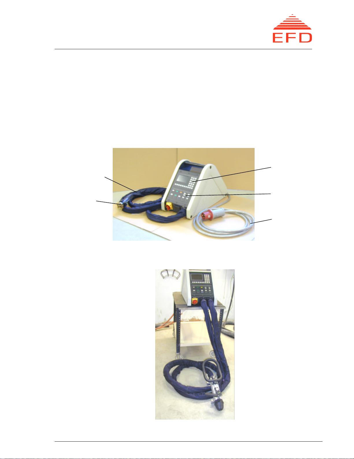
Figure 1. MINAC Standard 25/40 Induction Heater.
Figure 2.
MINAC Standard 50/80
Induction Heater with
HHT 400S.
Display and
keyboard
Switches and
indicators
Supply
power cable
HHT
Output
power cable

MINAC Systems Revision A
USER MANUAL 31 January 2005
63860.doc
© For reproduction rights, see cover page.
Page
2
2SAFETY INSTRUCTIONS, PRECAUTIONS AND HAZARDS
2.1 General
Safety instructions, including important information concerning the risks associated
with specific operations and recommendations on suitable precautions, are found
throughout the handbook where appropriate. The safety instructions are divided into
the two categories Warnings and Cautions:
WARNING!
Warning statements identify conditions or practices
that could result in injury or loss of life.
CAUTION!
Caution statements identify conditions or practices
that could result in damage to equipment and
surroundings.
Safety precautions must be observed during all phases of operation and
maintenance. Failure to comply with these precautions, or with specific WARNINGS
and CAUTIONS given elsewhere in this handbook, is a violation of the safety
standards of the design, manufacture and intended use of the equipment.
All personnel operating, maintaining or working in close proximity to the equipment
MUST thoroughly read, understand and obey the safety instructions that apply to this
equipment given by EFD Induction a.s. Only properly trained personnel who are
familiar with the technical handbook should be permitted to open the covers for
servicing this equipment.
WARNING!
Comply with all safety instructions. Failure to do so
can result in serious personal injury or damage to
equipment and surroundings.
Please note the following:
•To avoid personal injury, do not remove the equipment's covers or panels. Do
not, under any circumstances, operate the equipment without the covers and
panels properly installed.
•Switch off the equipment's power supply when it is not in use, and always retract
the mains plug prior to repair or maintenance.
•Always comply with all safety measures when handling electrical equipment,
including any national or international regulation.

MINAC Systems Revision A
USER MANUAL 31 January 2005
63860.doc
© For reproduction rights, see cover page.
Page
3
2.2 Electric Shocks
WARNING!
Electrical shocks can result in personal injury or loss
of life.
To avoid the risk of an electric shock, DO NOT:
•open the equipment covers during operation
•cut or damage the HF cable to the HHT
•touch the induction coil or coil adapter terminals after the power is turned on
•open the equipment covers during service without retracting the mains plug in
order to isolate the equipment from the main power supply.
WARNING!
Always retract the main-power plug before opening
the main fuse box.
2.3 Heated Objects
WARNING!
Heated objects can cause fire or burns.
The principle of induction heating is based on an alternating current flowing through
a coil and thereby generating a magnetic field that varies in magnitude with the
current. If an electrically conductive material is placed inside the coil, eddy currents
will be induced in the material. Due to the resistance of the material, heat is
developed in the region of the material through which the eddy currents flow.
Induction heating equipment can heat electrically conductive materials to a very high
temperature in a short time.
To prevent the danger of fire or burns, DO NOT:
•come in direct contact with heated objects before they have cooled
•wear or have metal objects about your body while operating, maintaining or
being in the presence of the inductance equipment when it is in use
•use or keep any combustible materials near the work area or heated objects.

MINAC Systems Revision A
USER MANUAL 31 January 2005
63860.doc
© For reproduction rights, see cover page.
Page
4
2.4 Electromagnetic Fields
WARNING!
Electromagnetic fields can be a health risk.
All induction heating equipment produces electromagnetic fields that are
concentrated inside the coils. The field’s strength depends on the current’s strength
and the number of turns in the coil. The field’s strength decreases with the square of
the distance from the coil.
To avoid hazards to personal health:
•Anyone with an implant, regardless of type, should consult a physician about the
effects of high-frequency electromagnetic fields on the implants. This also applies
to pregnant women.
•Persons with pacemakers, heart valves or metal pins, plates or other bone joining
devices, should avoid exposure to induction coils or areas with strong magnetic
fields if they have not consulted their physician beforehand.
•In general, all personnel should take great care not to come too close to the
induction coil when the equipment is in operation.
MINAC Systems Revision A
USER MANUAL 31 January 2005
63860.doc
© For reproduction rights, see cover page.
Page
5
3RESTRICTIONS IN USE
Only use the MINAC solely for its intended purposes under safe conditions and in
proper surroundings. Take great care when using the equipment. Heat only electrical
conductive materials. The presence of combustible materials involves a risk of fire.
The MINAC systems provide the following output power limitations for continuous
use and intermittent duty:
Equipment Continuous use Intermittent duty
MINAC 25, 25 Twin 25 kW 40 kW
MINAC 50/80 50 kW 80 kW
The maximum output powers are attainable only with low Q - magnetic steel. The
maximum duty factor is 0.5 and the maximum cycle time is 10 minutes. This means
that during a selected cycle, the unit can run at maximum output power only half of
the time (to a maximum of five minutes).

MINAC Systems Revision A
USER MANUAL 31 January 2005
63860.doc
© For reproduction rights, see cover page.
Page
6
4CONNECTING AND USING THE COIL
1. Make a good electrical contact between the coil and the HHT terminals — be
sure that the contact surfaces on both the coil and the HHT terminals are free of
dirt and oxides. If necessary, clean the surfaces with fine emery paper.
2. Be sure that the O-rings for the cooling water seals are free of any dirt or
damage.
3. When fitting the coil to the HHT terminals, maintain a parallel gap between the
coil and the HHT to avoid a short circuit.
4. Use only brass termination nuts on the HHT. Nuts of any other material are not
allowed. Torque the nuts to 9 Nm for 125S, and 14 Nm for HHT 240S and
HHT 400.
5. Once the flow of cooling water has been opened, hold the HHT so that the coil
points upwards. This prevents air bubbles from being trapped inside the
transformer, causing local overheating of areas which are not in contact with the
cooling water.
6. Prevent short circuits in the coil during operation by avoiding contact between
the coil and the workpiece. If contact is difficult to avoid, coat the coil with an
aluminum oxide (avoid oxide on the contact surface). This will reduce the risk of
short circuits. Coils supplied by EFD Induction a.s are already coated with an
aluminum oxide.
CAUTION!
The HHT is a vulnerable part of the equipment and
therefore must be handled with care.
CAUTION!
TEST RUN: When changing the induction coil or
heating new materials, run tests to check the
equipment settings.
Figure 3. Separate HHT and Coil Figure 4. Coil connected to HHT

MINAC Systems Revision A
USER MANUAL 31 January 2005
63860.doc
© For reproduction rights, see cover page.
Page
7
5MAN-MACHINE INTERFACE
5.1 Display and Keyboard
The display and keyboard together form the frequency converter's Man-Machine
Interface (MMI) and are located on the operating panel. A number of different menus
are available to the operator.
The starting point for access to these menus is the Main Menu (menu 1), which gives
an overview of the menus available.
Six of the menus are active. This means that the operator can enter different
variables/options such as control mode, time, sequence, setpoint, water shut-off,
extended operating range etc. These settings can be entered only in the “power off”
mode.
Four passive menus provide operational information. The operator can switch
between the different menus by using the function keys on the keyboard. If the unit is
a Twin model, it has one extra passive menu accessible to give information for both
outputs at the same time.
Additionally, there are two menus for the PIN code.
A. Display Sections:
The top row of the screen is divided into three areas. The left area displays the menu
identifier number, the center area displays the menu name, and the right area
indicates the returning key. When the PIN code is active, a “padlock” symbol is
displayed in the upper right corner.
The center part of the screen shows the contents of the selected menu. This display
can show a bar graph of relevant internal analog signals, timer or sequence data or
operator selectable values. The menu displays also contain explanatory text for the
different displays.
The bottom line or footer message shows operational and alarm messages from the
left.
If the unit is a Twin model, a square in the lower right corner shows which one of the
two outputs is displayed on the screen.
Dieses Handbuch passt für folgende Modelle
2
Inhaltsverzeichnis
Beliebte Heizung Handbücher anderer Marken


Empire Heating Systems
Empire Heating Systems WCC65 Bedienungsanleitung

Wetekom
Wetekom 92 86 43 Bedienungsanleitung

Desa
Desa SPC170-F Bedienungsanleitung

Watlow
Watlow Watrod Electric Tubular Heaters Bedienungsanleitung

Haverland
Haverland ECO-DRY GPS Series Stücklistenhandbuch

Stelpro
Stelpro ASILVC2060 Series Bedienungsanleitung