EIS 400 Series Betriebsanleitung

AENOR
Registrada
Empresa
ER-0634/1998
Q
U
A
L
I
T
Y
S
Y
S
T
E
M
C
E
R
T
I
F
I
E
D
Net
I
Electrónica Integral de Sonido
EIS
ENG
F
D
I
NL
N
2
28
54
80
106
132
KIT-PREMIUM
®
USER'S AND INSTALLATION MANUAL
HANDBUCH F.D. BENUTZER UND DIE INSTALLATION
MANUEL DE L'USUAIRE ET L'INSTALATEUR
GEBRUIKERSHANDLEIDING-INSTALLATIEHANDLEIDING
MANUALE D'USO E D'INSTALLAZIONE
BRUKERHÅNDBOK-INSTALLASJONSMANUAL
SERIE 400
42691 CONTROL UNIT


EIS 2
1. Introduction
2. Getting started
3. Installation
5. User Programming
8. Technical Specifications
4. Settings
7. Quick Reference Guide
6. Operation
9. Accesories
Wiring Diagram
4
5
8
10
25
12
26
16
27
3
Table of contents
ENG
Important Safety Instructions
Before installing the unit, please read and follow the instructions provided in the
Installation Manual included .
Before operating the unit, please read and follow the instuctions provided in the User´s
Manual thoroughly and save it for future experience.
WARNING -To reduce the risk of fire or electric shock:
install in accordance with the manufacturer’s instructions
do not expose this apparatus to rain or moisture
do not use this product near water
do not attempt to dissamble this unit
do not block any ventilation openings
do not install near any heat sources such as radiators, stoves or other
equipments that produce heat.
You are cautioned that any changes or modifications not expressly mentioned in this
manual could void your authority to operate this equipment.
This product has been designed and tested to provide reasonable protection against
harmful interference in residential installation. However there is no guarantee that
interference will not affect in a particular installation. In these cases, reorient the receiving
antenna, try to increase the separation between the equipment and the source of
interference and/or connect the equipment into an outlet on a circuit different from that to
which the source of interference is connected.
The entire risk of the installation, use, results and performance are borne by you.
When used as a mechanism to disconnect from the current network, a socket plug, or a
device connector; the disconnecting mechanism must be easily accessible at all times.
Protect the power cord from being walked on or pinched particularly at plugs,
convenience receptacles, and the point where they exit from the apparatus.
Only use attachments/accessories specified by the manufacturer.
as power-supply cord or plug is damaged,
liquid has been spilled or objects have fallen into the apparatus, the apparatus has been
exposed to rain or moisture, does not operate normally, or has been dropped.
Attention should be drawn to the environmental aspects of battery disposal.
Use a certified technician for installation, repair and/or maintenance of this equipment and
comply with all the regulations in force in each country. Servicing is required when the
apparatus has been damaged in any way, such
CAUTION
DO NOT OPEN
RISK OF ELECTRIC SHOCK
!

EIS
3Wiring diagram
CONNECTING TERMINALS
15Vdc Sound regulator power supply
Mass
2
4
05
06
04
N
F
Left loudspeaker output (red terminal/+)
Right loudspeaker output (red terminal/+)
Common loudspeaker ouput (black terminals/-)
230V Power supply
230V Power supply
FM tuner antenna signal
FM tuner antenna mass
A
M
EIS
POWER SUPPLY
TELECONTROL SOCKET
220V.max 400W
+
-
0506 4M04 2
+
-
A
CONTROL UNIT
EIS
2
14
3
27
6
5
CH FM
PRG
3
6
9
def
mno
wxyz
1
4
7
ghi
pqrs
2
5
8
0C
abc
jkl
tuv
76 cm
76 cm
16 W
+-
16 W
+-
Red Black
42FN
BlackRed
230V
112 95
F
F’
N02
4
03
2
1
0506 4M04 2A
426 91
112 95
426 91
194 _5
112 98
CONTROL UNIT
ON / OFF
EIS
2
14
3
27
6
5
CH FM
PRG
3
6
9
def
mno
wxyz
1
4
7
ghi
pqrs
2
5
8
0C
abc
jkl
tuv
230V
16 W
-+
16 W
+-
ENG
KIT-PREMIUM
®
SERIE 400
42691 CONTROL UNIT

4
1. Introduction
The new is here. It provides the finest features offered by the EIS
400 Series, available in the convenient form of a kit.
Like the 400 Series, the is user-friendly in design. Its clear and
easily accessible menus allow the user to failor the settings according to the needs of each
client. The direct FM tuning, the adjustable lighting, the screen with bigger letters and
numbers, the choice of language, etc. are just some of the functions available in this
customer-centered design.
The advantages of the kit are many. Primarily, it is easy to assemble. All the parts required
for installation are included in the kit: the control unit, the cables, the power supply, the
housing case, etc.
kit
kit
kb
kb
sound premium
sound premium
®
®
What else does the offer? It was designed for people who want to enjoy sound in radio or music in areas of
the home with no television or stereo system, no sound pre-installation and who have no desire to undergo major improvements.
The is the ideal accessory to enjoy the best possible sound in the kitchen and bathroom by means of a control unit that
blends right into the decor.
As always and with the
kit
kit
kit THE CUSTOMER ONLY HAS TO LISTEN.
QUALITYkb
kb
kb
sound premium
sound premium
sound premium
®
®
®
EIS
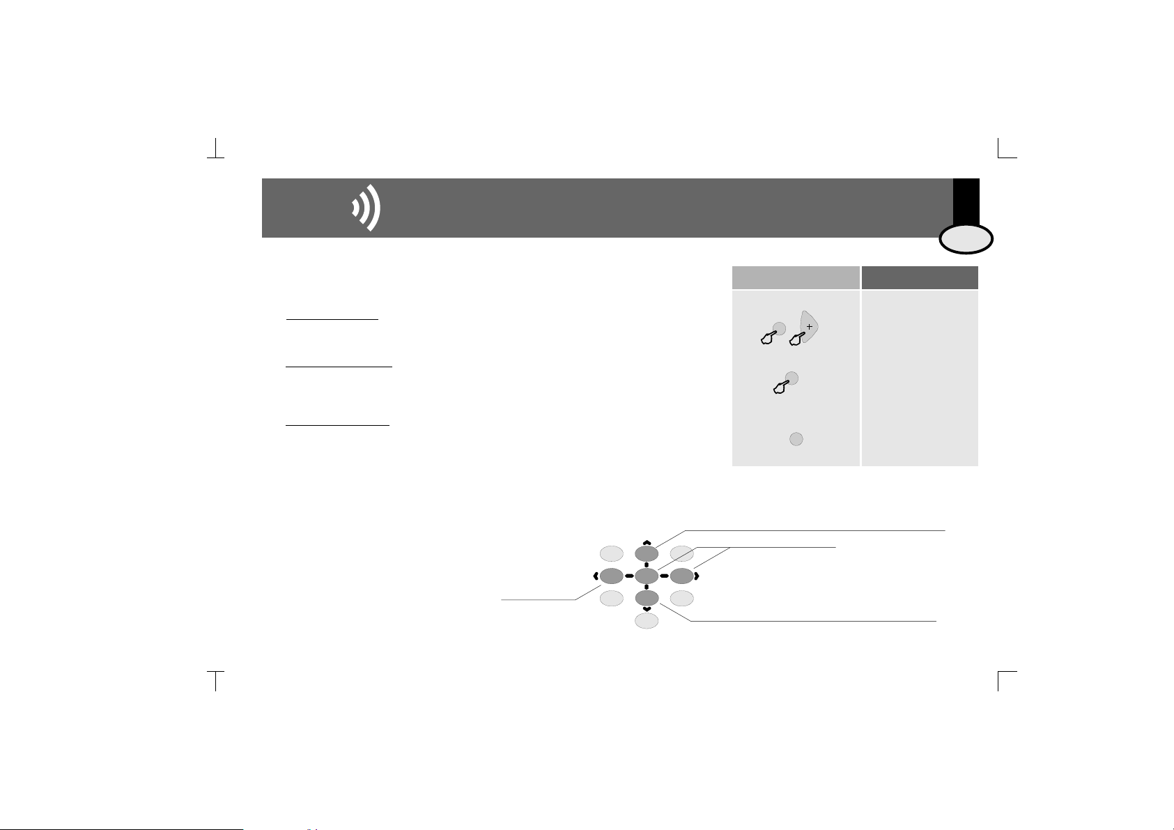
The symbol over a key
means the key should be pressed
for the time specified
Some keys serve the function of a cursor to scroll through
the menus. When the key in question is used as a cursor,
it will be illustrated with the cursor symbols that appear
on the face of the control unit. 2
54
8
6
abc
jkl
ghi
tuv
mno
In some cases it will be necessary
to press two keys simultaneously
to execute a
particular
command. 2’’
PRG
KEYS TO UNDERSTANDING THE SYMBOLS
USED IN THIS MANUAL
5’’
ENG

To turn on, press the on/off key. The display will light up and
the icon enabled.
To select Discman input for the control unit, press CH
EIS
5
9
wxyz
4
ghi
7
pqrs
FM 94.70
Users
Once the control unit has been installed it is ready for normal
operation.
Once the control unit is connected to the mains, it will remain
powered even it is in OFF state. That means that the OFF state
(as indicated in this manual) really means a “standby” state
2.1 The first time...
Installers
The control unit must be installed once power is fed for the first
time. By default, the control unit is set to stereo for 16
loudspeakers. To configure other settings use the installation
menu option 3.2.1. - Mono/Stereo and 3.2.2. - Audio Output.
W
Key Sequence Display Visual
07:18
CH
vol 55
96.70
To adjust the volume
To select the tuner, press FM
To tune to a station, key in the station frequency followed by
the FM key. For example, to tune to the station at 94.7 MHz.
To automatically seek stations
The + - keys have multiple functions. The default function is to adjust the
volume. If no key is pressed on the keypad a few seconds after an
operation, the default function resumes. FM
2. Getting Started
95.50
FM
ENG

EIS
2. Para empezar 6
2. Getting Started
Key Sequence Display Visual
instal
Installation Menu
This menu stores information regarding the parameters that affect the installation's proper
operation. This programming should be done by a specialized technician.
There are three menus to program different access levels.
2.2 Programming Menus
2.2.1 Three Access Levels
2’’
PRG
PRG
2’’
PRG
Configuration Menu
This menu stores information regarding the personalized operating mode for each user.
Modifying this menu does not vitally affect the installation's operation and once the settings
are defined there will be no need to change them.
Programming Menu
This menu stores information regarding the features that can be programmed by the user
and which can be easily modified.
config
progr
EIS
The programming menus are structured as levels of menus and submenus.
Once in a menu, the following keys can be used to scroll
through the list of options.
2.2.2 Scrolling Through the Menus
Goes back to the previous option on the same level
Goes into the level
Exits the level
Goes forward to the next option on the same level
21
54
8
7
0C
3
6
9
abc
jkl
ghi
pqrs
tuv
def
mno
wxyz
ENG

EIS
7
When the item to be programmed appears on the display it will be
flashing, thus indicating it is ready to be modified. If there are several
choices possible (for example, the days of the week, the digits of a date),
the + and - keys can be used to scroll back and forth between the items.
2. Getting Started
Key Sequence Display Visual
PRG
0C1’’
The numeric keys can also be used to modify the item. In addition to using
the numeric keys, in some cases the + and - keys themselves can be used
to modify an item to be programmed.
To store the new setting, press PRG. The item will flash quickly, indicating
that the new setting has been stored.
To delete a setting that has been entered, press the ZERO key for 1”.
To exit a programming option without saving a setting, press ON/OFF.
PRG
2
abc
1
2
abc
PRG
2’’
To access programming menu option “adjust the tuner seek sensitivity”
To access the configuration menu option “personalize your greeting”
To access the installation menu option “select loudspeaker output
impedance”
2.2.3 Immediate Access to a Menu Option
As an alternative to scrolling through the menus to reach an option, you can directly key in
the option code followed by the menu access key (see the list of codes in 7. CODES AND
TABLES).
2
abc
PRG
2’’
ENG

8
EIS
3.1 Wiring Diagram
·
·
·
·
·
If the room is monophonic, connect any of the speakers and set the control unit to MONO. (See 3.2.1. Mono/Stereo Installation)
8 speakers can be connected to the control unit outputs. In this case, the control unit must be set to 8 . (See 3.2.2. Audio Output
Installation).
To connect the FM antenna, connect a 76 cm wire to terminal A or connect a 75 antenna input to terminals A (signal) and M (mass).
If it is necessary to connect an amplifier or power stage to a control unit's output, the control unit must be set to AMPLIFIER. (See 3.2.2.
Audio Output Installation). Connect the amplifier to terminals 2, 4, 05 and 06 on the control unit.
All wire sections are 0.25 mm except supply wires (terminals 2 and 4), which are 1 mm. The network tapping wires are standard.
W W
W
Installation involves three elements: a power supply, a control unit and loudspeakers. See on page 3.
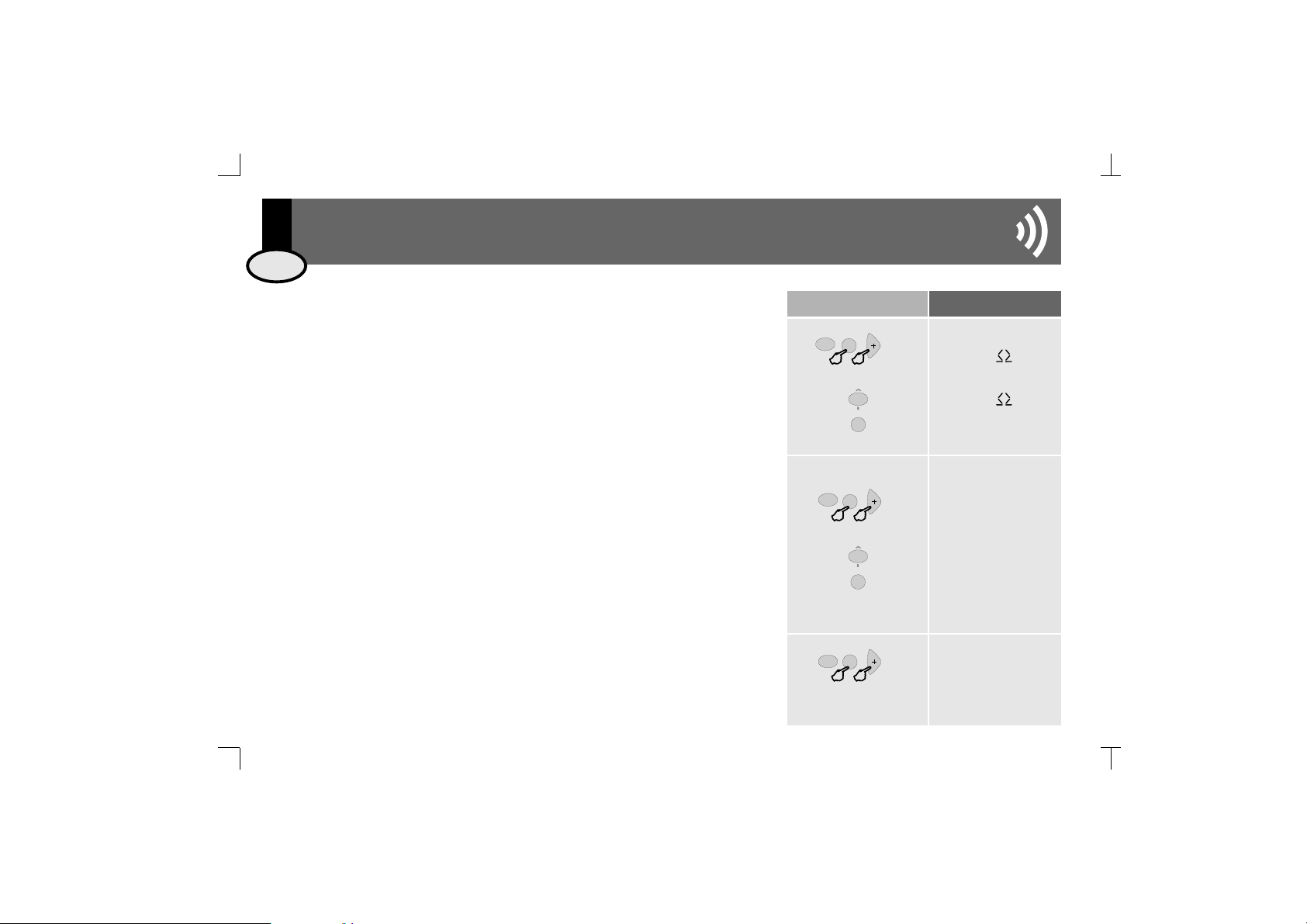
3.2.1 Mono/Stereo
Defines whether the control unit's audio output (terminals 04, 05, 06) is connected in
mono or stereo mode. In a control unit in stereo, outputs 05 and 06 respond to the left
and right channels. In a control unit in mono, both outputs are identical and can
therefore be used interchangeably.
To change the output setting to mono
Store
Key Sequence Display Visual
stereo/mono
stereo
mono
2
abc
PRG
2’’
PRG
3.2 Installation Menu
The following information is, in its totality, the installation data for the control unit. To
modify the data, access the installation menu of the control unit itself.
See 7. CODES AND TABLES.
1
3. Installation
ENG

EIS
93. Installation
Key Sequence Display Visual
on
loading data
2
abc
PRG
delete installation
off
version soft
software, 112702, 141211
Shows control unit’s software version.
3.2.3 Deleting Control Unit Installation. Manufacturer Reset.
3.2.4 Knowing the Software Version
Deletes all settings and programming data from the control unit, restoring manufacturer
default settings.
Once the control unit starts up, the manufacturer default settings are enabled.
To activate delete process
To initiate the process
2’’
PRG
2’’
PRG
3
def
4
ghi
16
8
3.2.2 Audio Output
Defines the impedance connected to the control unit's audio output (terminals 04, 05, 06)
between the following options: 16 passive loudspeaker
8 passive loudspeaker
amplifier
line
W
W
To change the setting to 8 W
Store
audio output
2
abc
PRG
PRG
2’’
2
abc
ENG
Dieses Handbuch passt für folgende Modelle
2
Inhaltsverzeichnis
Sprachen:
Beliebte Steuereinheit Handbücher anderer Marken

Festo
Festo Compact Performance CP-FB6-E Stücklistenhandbuch

Elo TouchSystems
Elo TouchSystems DMS-SA19P-EXTME Bedienungsanleitung

JS Automation
JS Automation MPC3034A Bedienungsanleitung

JAUDT
JAUDT SW GII 6406 Series Kurzanleitung

Spektrum
Spektrum Air Module System Bedienungsanleitung

BOC Edwards
BOC Edwards Q Series Bedienungsanleitung