EMTOP SOM-IMX8M-MINI Bedienungsanleitung

1
SOM-IMX8M-MINI

2
Contents
SOM-IMX8M-MINI.............................................................................................................................. 1
1. General.................................................................................................................................. 3
2. Features.................................................................................................................................4
2.1 SOM-IMX8M-MINI.....................................................................................................4
2.2 DEV-IMX8M-MINI...................................................................................................... 5
3. Application.............................................................................................................................6
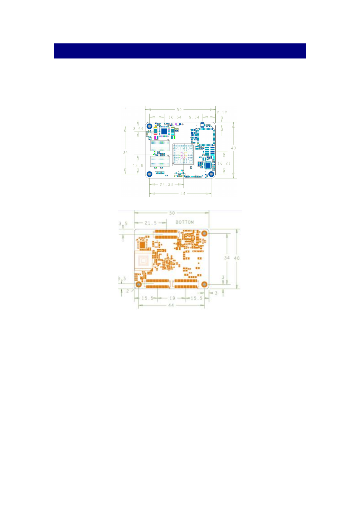
4. Mechanical Dimension........................................................................................................7
5. Electrical Characteristics.................................................................................................... 8
5.1 Working Temperature................................................................................................8
6. Hardware Overview............................................................................................................. 8
6.1 System Components................................................................................................. 8
6.2 Functional Block Diagrams.....................................................................................10
7. Interface Description......................................................................................................... 11
7.1 BTB ON Connector..................................................................................................11
7.2 WiFi/BT Antenna Connector...................................................................................12
8. Pinout Description Table...................................................................................................13
9. Power Supply And System Resets................................................................................. 20
9.1 Power Source...........................................................................................................20
9.2 Power Control and Monitoring...............................................................................20
9.3 System power.......................................................................................................... 20
9.4 Power Consumption Typical Values.....................................................................20
10. System Resets................................................................................................................. 21
10.1 Power-on Reset.....................................................................................................21
10.2 Brown-out Reset....................................................................................................21
10.3 Software Reset...................................................................................................... 21
10.4 External Reset....................................................................................................... 21
11. Boot Mode.........................................................................................................................21
12. Trace impedance recommendations............................................................................22
13. High-speed signal trace length compensation........................................................... 22
14. Circuit Example................................................................................................................24
14.1 Reset In...................................................................................................................24
14.2 Power Key.............................................................................................................. 24
14.3 Boot Mode.............................................................................................................. 24
14.4 Giga Ethernet.........................................................................................................25
14.5 TF Card................................................................................................................... 26
14.6 SOM Power-Up Enable........................................................................................26
14.7 PCIe Clock..............................................................................................................27

3
1. General
This document describes the hardware architecture of the SOM-IMX8M-MINI Module.
The SOM-IMX8M-MINI System-On-Module (SOM) board is based on NXP’s energy
efficient i.MX 8M Mini series processor. For i.MX 8M Mini series processors which has up to 4
x Cortex-A53 cores capable at running up to 1.8 GHz and one Cortex-M4 core capable at
running up to 400 MHz core for low-power and real-time operation.
On-board up to 2GB DDR4, up to 64GB eMMC and a WiFi / Bluetooth module, and with MIPI
DSI display driver, MIPI CSI camera receiver, flexible audio interfaces and comprehensive
communication features. The SOM-IMX8M-MINI Module is a fully-integrated system that helps
you build your professional embedded systems rapidly.
Support Linux kernel, Yocto Project file-system, Debian and Android run on the Cortex-A core,
and Real-time OS such as UCOS and FreeRTOS run on the Cortex-M core.
Comes with detailed user manual, ready-made system, and friendly technology support. We
are able to provide customize based on this SOM module for various application.

4
2. Features
2.1 SOM-IMX8M-MINI
Picture2.1 Top side of SOM-IMX8M-MINI
Picture2.2 Bottom side of SOM-IMX8M-MINI
oUp to Quad-core ARM Cortex-A53
o64-bit Armv8-A architecture
oTarget frequency up to 1.8GHz
o2D/3D GC520L
oMedia Processing Engine (MPE) with NEON technology
oFloating Point Unit (FPU) with support of the VFPv4-D16 architecture

5
oOne Cortex-M4 up to 400MHz
Wi-Fi 1x1 (802.11b/g/n/ac 2.4/5GHz)
Bluetooth 5.0
From 8 to 64GB eMMC
Up to2GB DDR4
64M bit Quad SPI Flash on-board
3*60Pin 0.5mm pitch BTB connectors
Up to 75xGPIO (including SPI,I2C,PWM,UART,SAI, and SDIO)
2.2 DEV-IMX8M-MINI
Picture2.3 DEV-IMX8M-MINI
12V Power IN x 1
USB 2.0 Host x 2
USB OTG x 1
USB 2.0 Host (4 Pin Connector) x 1
UART:
oUART2 (TTL, For Debug)
oUART3 (TTL, For User)
oUART4 (TTL, For User)
I2C x 3

6
USB Touch x 1
MIPI-CSI x 1
Fan 5V port x 1
MIPI-DSI x 1
Buzzer x 1
SIM Card x 1
TF Card x 1
Mini PCIE Interface x 1, For 4G module and PCIE module
CAN Bus x 1
RS485 Bus x 1
Input Terminal x 2 PIN (With Isolation)
Output Terminal x 2 PIN (With Isolation)
Headphone Output/MIC In x 1
SPDIF Out x 1
1x Gigabit Ethernet on-board
3. Application
HMI
Medical appliances
Industrial automation
Weighing Scales
Smart Toll Systems
Educational Consoles

7
4. Mechanical Dimension
Size: 50 x 40 x 7.3 mm
PCB Parameter:8 layer design, lead-free soldering process
Weight: 12g
Picture4.1 Mechanical Dimension of Top side
Picture4.2 Mechanical Dimension of Bottom side

8
5. Electrical Characteristics
5.1 Working Temperature
Table5.1 Working Temperature
Specification
Minimum Operating Temperature
(℃)
Operating Temperature
(℃)
Commercial Grade
0
70
Industrial Grade
-40
+85
Note:
A heat sink may need for some applications
6. Hardware Overview
6.1 System Components
Table6.1 Hardware Overview
Feature
Details
i.MX8M MINI SOC
Arm Cortex-A53 MPCore platform
Quad symmetric Cortex-A53 processors,
including:
•32 KB L1 Instruction Cache
•32 KB L1 Data Cache
•Media Processing Engine (MPE)
•Floating Point Unit (FPU)
Support of 64-bit Armv8-A architecture
•512 KB unified L2 cache
•Target frequency of 1.8GHz
Arm Cortex-M4 core platform
•16 KB L1 Instruction Cache
•16 KB L1 Data Cache
•256 KB TCM
Graphic Processing Unit (GPU)
•GC NanoUltra frequency up to 800 MHz
•OpenGL ES 2.0
•2D GC520L
Video Processing Unit (VPU)
•VP9,VP8,AVC,H.265,H.264 decoder
•VP8, AVC,H.264 encoder
Audio
•S/PDIF Input and Output
•SAI modules supporting I2S,AC97,TDM
On-chip memory
•Boot ROM (256KB)

9
•On-chip RAM (256KB + 32KB)
Memory and storage
DDR SDRAM
•2GB DDR4 SDRAM (32-bit bus width)
•1200MHz maximum DDR clock
•Interfaces directly to the iMX8M MIPI build-in
DDR controller
eMMC
•8GB NAND eMMC flash memory
•8-bits MMC mode
•Conforms to JEDEC version 5.0 and 5.1
SPI Flash
•64M bit SPI flash memory
•104MHz Single, Dual/Quad SPI clocks
•More than 100,000 erase/program cycles
•More than 20-year data retention
Expandable flash (MicroSD)
•Meets SD/SDIO 3.0 standard Runs at 4-bits
•Supports system boot from SD card
Network & Wireless
Ethernet
•On-board 10/100/1000 Mbps Ethernet PHY
Wi-Fi
AzureWave AW-CM256SM module:
•Wi-Fi 1x1 (802.11a/b/g/n/ac 2.4/5GHz)
•SDIO 3.0
•High speed wireless connection up to
433.3Mbps
Bluetooth
AzureWave AW-CM256SM module:
•Bluetooth 5.0 (supports Bluetooth low-energy)
•High-speed UART
•PCM audio
Hardware Interface
I/O connectivity
•1x single lane PCI Express Gen 2
•2x USB2.0 OTG with integrated PHY
•1x SDIO supporting MMC 5.1, SDIO 3.01
•1x Gigabit Ethernet with integrated PHY
•3x UART
•3x I2C
•2x ESPI
Display Interfaces
• 4-lane MIPI DSI interface
Camera
• 4-lane MIPI CSI interface

10
6.2 Functional Block Diagrams
The following figure is a functional block diagram of the SOM-IMX8M-MINI:
Picture6.1 Functional Block Diagrams
Picture6.2 i.MX 8M Mini system block diagram
Inhaltsverzeichnis
Beliebte Steuereinheit Handbücher anderer Marken

Festo
Festo Compact Performance CP-FB6-E Stücklistenhandbuch

Elo TouchSystems
Elo TouchSystems DMS-SA19P-EXTME Bedienungsanleitung

JS Automation
JS Automation MPC3034A Bedienungsanleitung

JAUDT
JAUDT SW GII 6406 Series Kurzanleitung

Spektrum
Spektrum Air Module System Bedienungsanleitung

BOC Edwards
BOC Edwards Q Series Bedienungsanleitung


