http://www.GuitarAmplifierPCBs.com
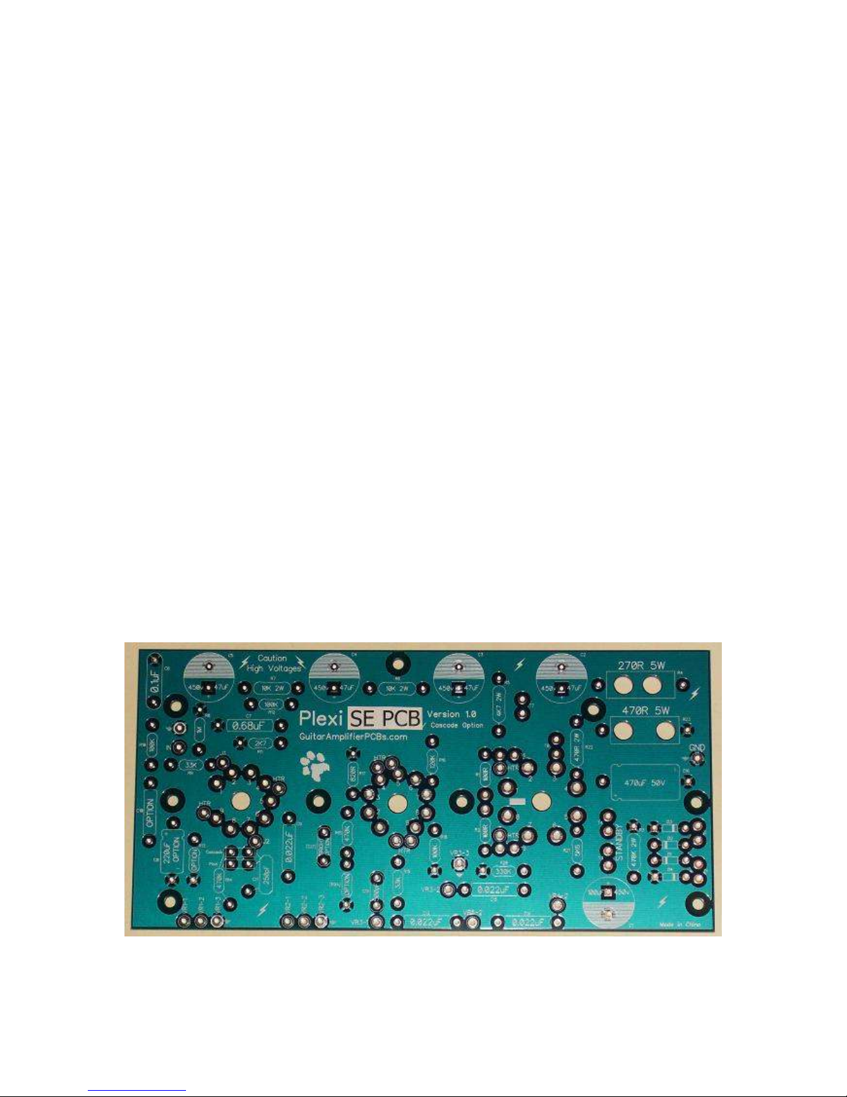
Plexi SE PCB Valve Junior Conversion Version
Build Manual 3 August 009
4 of 34
Table of ontents
1. Introduction ............................................................................................................................. 2
2. Electrical Shock Warning........................................................................................................ 3
3. Disclaimer of Liability .............................................................................................................. 3
4. Project Overview..................................................................................................................... 5
4.1 Here’s what you’ll need: ................................................................................................. 5
4.1.1 Parts: ..................................................................................................................... 5
4.1.2 Tools: ..................................................................................................................... 5
4.1.3 Supplies: ................................................................................................................ 5
5. Let’s get started…................................................................................................................... 6
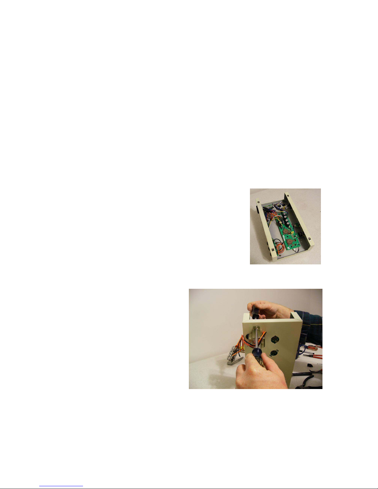
5.1 Remove the EVJ chassis ............................................................................................... 6
5.2 Remove the EVJ’s Stock Components .......................................................................... 7
5.2.1 Remove the Tubes and Tube Retainers ............................................................... 7
5.2.2 Remove the Output Transformer from the Chassis .............................................. 7
5.2.3 Clean Up the Power Transformer.......................................................................... 8
5.2.4 Remove the Volume Potentiometer ......................................................................
5.2.5 Remove the Stock EVJ Circuit Board....................................................................
6. Prepare the Chassis ............................................................................................................. 11
6.1 Layout and Drill ............................................................................................................ 11
6.1.1 Layout the Plexi SE PCB for Drilling ................................................................... 11
6.1.2 Layout the Faceplate for drilling .......................................................................... 12
6.1.3 Drilling the Chassis.............................................................................................. 13
7. Plexi SE PCB ........................................................................................................................ 13
7.1 Assemble the Plexi SE PCB ........................................................................................ 13
7.1.1 PCB Standoffs ..................................................................................................... 14
7.1.2 Tube Sockets....................................................................................................... 14
7.1.3 Spade Connectors............................................................................................... 15
7.1.4 Diodes.................................................................................................................. 16
7.1.5 The “Plexi Preamp”.............................................................................................. 17
7.1.6 The “Cascade Preamp” ....................................................................................... 18
7.1.7 Wiring the Heaters............................................................................................... 1
7.1.8 Filter Capacitors .................................................................................................. 21
7.1. Bypass Capacitors............................................................................................... 22
7.1.10 Install the Remaining Components ..................................................................... 23
7.1.11 Input Jack ............................................................................................................ 24
7.1.12 Control Leads ...................................................................................................... 25
8. Putting it All Together............................................................................................................ 26
8.1 Install the New Components ........................................................................................ 26
8.1.1 Hookup the Plexi SE PCB ................................................................................... 26
. Turn on the Power ................................................................................................................ 2
.1 Check Your Work ......................................................................................................... 2
.1.1 Take a Break ....................................................................................................... 2
.1.2 Visual Inspection ................................................................................................. 2
.2 Power Up without Tubes .............................................................................................. 30
.2.1 The First Power Up.............................................................................................. 30
.3 Power Up with Tubes ................................................................................................... 32
.3.1 The Real Test ...................................................................................................... 32
10. Finish Things Up............................................................................................................... 34
10.1 Re-Assemble the Amp ................................................................................................. 34