ESCALADE Prince T8830 Bedienungsanleitung

MODEL NO.
T8830
Escalade® Sports products may be manufactured and/or licensed under the following patents.
6120397, 5816957, 5769744, 5119741, 4911085, 4717157, D460140, D420563, 8414431
Additional patents may be pending. One or more of the listed patents and/or pending patents may cover specific product.
A S S E M B L Y I N S T R U C T I O N S
Contact Escalade® Sports customer service department at:
Phone: 1-866-873-3528 Toll-Free!
Fax: 1-866-873-3533 Toll-Free!
E-mail: [email protected]
Please Do Not Return This
Product to the Store!
2015 Escalade Sports
2L-4238-01
“ S P O R T ”
T A B L E T E N N I S T A B L E

Prince (tm) is a trademark of Prince Sports, LLC.
© 2015 Prince Sports, LLC.
www.princetennis.com
P R E - A S S E M B L Y T I P S
Contact Escalade® Sports customer service department at:
Phone: Toll – Free !
Fax: 1-866-873-3533 Toll – Free !
E-mail: tabletennis@escaladesports.com
Mailing Address (correspondence only):
Escalade Sports
PO Box 889
Evansville, IN 47706
Please Do Not Return This Product To The Store!
Please visit our Website at:
www.escaladesports.com
ON-LINE TROUBLE SHOOTING TECHNICAL ASSISTANCE
ON-LINE PARTS REQUESTS FREQUENTLY ASKED QUESTIONS
ADDITIONAL ESCALADE®
SPORTS PRODUCT INFORMATION
1-866-873-3528
2015 Escalade Sports
2L-4238-01
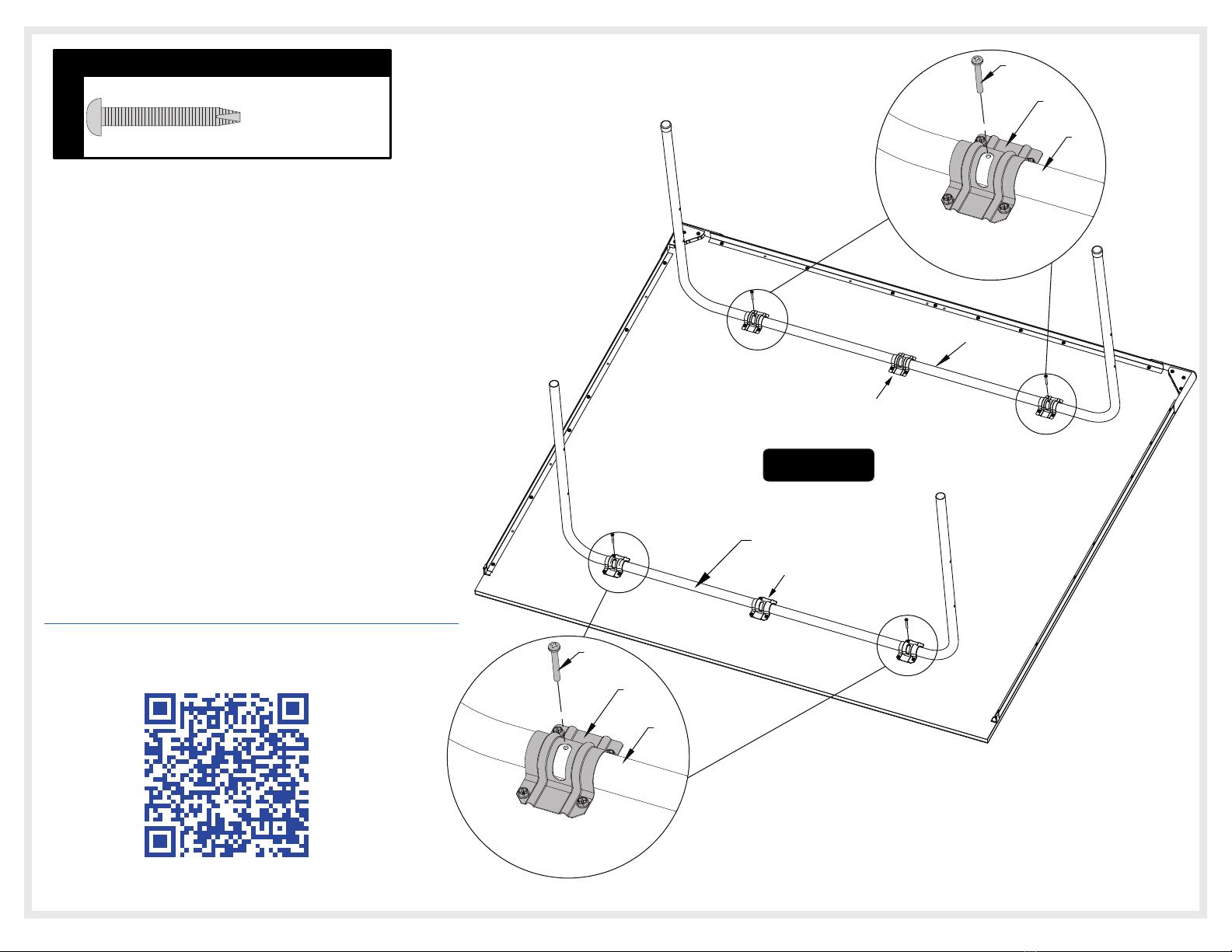
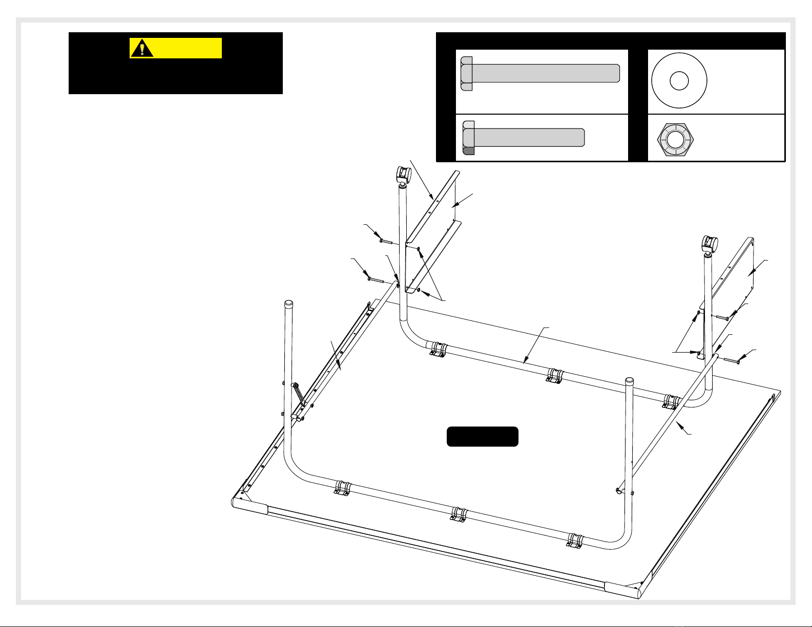
1. Read this manual carefully before starting assembly. Read each step completely before beginning each step.
2. Some smaller parts may be shipped inside larger parts. Check inside all parts and cartons before assembling or ordering
parts.
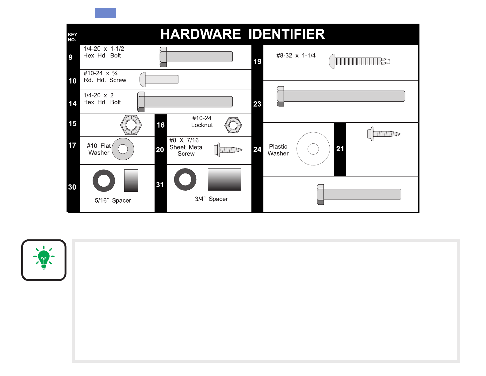
3. To make assembly easier, use the Hardware Identifier on page 3 to identify and sort all fasteners. Check all cartons for
kits. All hardware may not be located in one kit.
4. Do not tighten hardware until instructed to do so. If hardware is tightened too soon, mounting holes may not align and
parts may not easily fit together. Leave locknuts slightly loose until you are instructed to tighten them.
5. Tools required for assembly: Phillips Screwdriver, one 3/8” Wrenches, Two 7/16” Wrenches (Ratchet and 3/8”, 7/16” Sockets are
recommended and can be substituted for wrenches), Rubber Mallet or Hammer.
6. An electric screwdriver is helpful in assembly. However, please set at low torque and use caution because you could over-tighten the
and strip the screws out of the wooden table top.
7. Save these instructions and your proof of purchase (receipt) in the event that the manufacturer has to be contacted for
replacement parts.
P R E - A S S E M B L Y T I P S

(Qty. 6)
1/4-20 Locknut
(Qty. 16)
(Qty. 2)
(Qty. 4)
(Qty. 2)
(Qty. 4) (Qty. 4)
(Qty. 2)
(Qty. 84) (Qty. 8)
S.M.S. (Qty. 8)
29 1/4-20 x 1 3/4”
Hex Hd. Bolt
Qty. 2
(Qty. 4)
1/4-20 x 2 3/4 Hex Head Bolt
#8 x 5/8 Sheet
Metal Screw
(Qty. 12)
A. An electric screwdriver is helpful in assembly. However, please set to low torque and use caution because you could
over-tighten the hardware and strip the screws.
B. Indentation mounting guides are small so look closely when attaching hardware.
C. Table top can be set on top of two saw horses. Although this will make assembly easier it is not necessary to complete
assembly. Always use shipping container to protect the painted surface of the table top.
CAUTION: Make sure that the table top is secure on sawhorses and NEVER leave the table top unattended.
ASSEMBLY TIPS
Sorting your hardware ahead of time will speed up assembly time. Sort all your
hardware now so it will be ready before you start assembly.
NOTE:
3

2. Align U-Support (#7) and U-Leg (#2) on Table
Top as shown in Figure 1.
1. Lay table top #1 painted side down, on a smooth, flat
surface. Use the shipping container to protect the
painted surface of the table top.
End Rail Mounting
Indentations
Note: Indentations are
small so look closely.
1
2
13
7
3. Put plastic caps (#13) on the end of
U-Leg (#2). See Figure 1.
NOTE: “U-Leg” (#2) is larger and Wider
than the “U-Support” (#7). The U-Leg
should be installed on the end of the table
half with the end rail mounting holes.
(U-Support)
(U-Leg)
Note: U-Leg (#2) is larger and
Wider than the U-Support (#7).
1
Figure
Note: Indentations are
small so look closely.
ASSEMBLY TIP
The following pages will have a picture of the
Hardware Needed (to scale) along with the
Quantity, Key# and Description. You can lay the
hardware on the picture to identify the hardware.
ASSEMBLY TIP
Table top can be set on two saw horses. Although this will make
assembly easier it is not necessary to complete assembly. Always use
shipping container to protect the painted surface of the table top.
CAUTION: Make sure that the table top is secure on the
sawhorses and NEVER leave the table top unattended.
CAUTION:
4

4.
Align the holes in the U-clips #3 with the
indentations in table top assembly and secure
with four screws #20 per U-clip as shown. All
four holes in each U-Clip must align with four
Indentations in top. See Figure 2, Detail A and
Detail B.
20
3
IMPORTANT:
Slot in
U-Clip
Detail A
Be sure that slot in the three U-clips #3 all
face the same direction as shown. (Toward
the end of the table with no stripe.)
5
3
Be sure that slot in the three U-clips
#3 all face the same direction as
shown. (Toward the end of the
table with no stripe.)
Slot in
U-Clip
3
20
Detail B
7
2
3
7
Note: U-Leg (#2) is Taller and
Wider than the U-Support (#7).
Make sure they are assembled
exactly as shown. If not, there will
be a large gap between table
halves and table will not operate
properly!
(U-Support)
(U-Leg)
(U-Support)
Note: This is the end of the table
with no stripe or indentations.
WHEN ASSEMBLING TABLE, IT IS EXTREMELY IMPORTANT THAT THE U-CLIPS
(#3) BE TURNED AS SHOWN HERE. IF U-CLIPS ARE TURNED INCORRECTLY,
YOU WILL DO IRREPARABLE DAMAGE TO YOUR TABLE WHEN YOU ATTEMPT
TO OPEN IT TO THE PLAYING POSITION.
2
Figure
IF USING AN ELECTRIC SCREWDRIVER PLEASE SET AT LOW TORQUE AND USE CAUTION
BECAUSE YOU COULD OVER-TIGHTEN THE HARDWARE AND STRIP SCREW IN WOOD
DOING IRREPARABLE DAMAGE TO THE TABLE. DO NOT OVER TIGHTEN SCREWS!
20
HARDWARE NEEDED
#8 X 7/16” Screw
(Qty. 24)
IMPORTANT:
NOTICE
NOTICE

5. Lay out Side Rails #25 and End Rail #26, around edges
of table top as shown in Figure 3.
6. Slide Left #33 and Right #32 Vinyl End Caps onto the
ends of the Side Rails #25 as shown in Detail C.
7. Line up holes in rails with indentations in top
and secure using eighteen screws #20. See
Figure 3 & Detail C.
8. Lay Corner Caps #22 on table as shown in
Figure 3. If Corner Cap sticks above the
table top surface of the table, flip over so
the shorter distance is against edge. Secure
to bottom of table with three Screws #21.
See Detail D.
25
26
21
25
Note: Rails attach
with #20 screws
7
Note: Rails attach
with shorter #20
screws
20
33 (LH)
20
Detail C
Shorter Distance
Detail D
Longer Distance
20
32
(RH)
3
Figure
20
HARDWARE NEEDED
#8 X 7/16” Screw
(Qty. 18)
20
HARDWARE NEEDED
#8 X 5/8” Screw
(Qty. 6)
21
Note: This is the end of the
table with no rails.
Shorter Longer
Note: Corner Caps
attach with longer
#21 screws
20
6
IF USING AN ELECTRIC SCREWDRIVER PLEASE SET AT LOW TORQUE AND USE CAUTION
BECAUSE YOU COULD OVER-TIGHTEN THE HARDWARE AND STRIP SCREW IN WOOD
DOING IRREPARABLE DAMAGE TO THE TABLE. DO NOT OVER TIGHTEN SCREWS!
NOTICE

2
19
3
7
Detail E
Note: Wear safety glasses for Step 9.
If you want to see a video on how to insert Screw (#19) go to:
http://www.escaladesports.com/customer-service/videos.html
7
9. Insert Screw #19 through slot in U-Clip #3 and the into U-
Support #7. Thread it all the way into U-Support #7 until it
touches the back of the tube. There should be about 3/8
inch of screw #19 left sticking out. Do not insert screw in
middle #3 U-Clip. See Figure 4 and Detail E. Repeat
for U-Leg (#2) and U clip (#3). See Detail F.
Or
Scan with your smartphone:
Note: Rotate U-Support #7
until you see the screw hole in
the slot of U-clip #3. Slide U-
support #7 side to side and
front to back if necessary.
19
3
2
Detail F
Note: Rotate U-leg #2 until
you see the screw hole in
the slot of U-clip #3. Slide
U-leg #2 side to side and
front to back if necessary.
Note: Rotate U-Support #7 until you see the screw
hole in the slot of U-clip #3. Slide U-support #7 side
to side and front to back if necessary.
4
Figure
20
HARDWARE NEEDED
19
HARDWARE NEEDED
#8-32 X 1 1/4
Phillips Head Screw
(Qty. 4)
DO NOT insert Screw
#19 in middle #3 U-clip.
DO NOT insert Screw
#19 in middle #3 U-clip.
7

7
4
Detail G
Figure 5A
First Table Top
12. Attach slotted end of safety strap #6 to INSIDE of Leg #2
using one bolt #29, one spacer #30, one washer #24, and
one hex nut #15. Tighten hardware until snug but do not
overtighten. Tubes must pivot freely. See Detail H2.
Important! Do NOT put other
safety strap #6 on this table
half. It will be installed on
second table half later.
23
4
15
31
2
4
15
1/4” Locknut
(Qty. 3)
29 1/4-20 x 1 ¾” Hex Head Bolt
(Qty. 1)
1/4-20 x 2 ¾” Hex Head Bolt
(Qty. 2)
30
3/4” Spacer
(Qty. 2)
31
5/16” Spacer
(Qty. 2)
HARDWARE NEEDED
24 Plastic Washer
(Qty. 2)
1/4-20 x 1 1/2 Bolt
(Qty. 1)
9
HARDWARE NEEDED
15
23
29 30
24
15
4
(Longer)
(Longer)
31
Detail H2
30
6
924 4
Detail H1 15
10. Attach safety strap #6 to linkage #4. Be sure to attach on the end of
linkage with TWO holes. Use one bolt #9, one washer #24, one
Spacer #30, and one hex nut #15. See Detail H1.
Note: This is the end of the
table with no rails.
11. Attach end of linkage #4 with the attached Safety Strap #6 INSIDE of
U-Leg #2 as shown in Detail H2. Secure through end hole with bolt
#23, Spacer #31 and locknut #15. Tighten hardware snug enough to
keep table stable but do not overtighten. Tubes must pivot freely.
2
2
13. Attach linkage #4 INSIDE other end of U-Leg #2 as
shown in Detail G. Secure through end hole with bolt
#23, plastic spacers #31 and locknuts #15. Tighten
hardware snug enough to keep table stable but do not
overtighten. Tubes must pivot freely.
6
8

14. Tap caster sockets #12 into U-support #7 until flange on
sockets touches the edge of the tube. See Figure 5B.
15. Insert casters #11 into caster sockets #12.
DO NOT HIT CASTER SOCKET #12 DIRECTLY WITH
A HAMMER! SET A PIECE OF WOOD ON CASTER
SOCKET AND HIT PIECE OF WOOD TO DRIVE
CASTER SOCKET INTO U-SUPPORT #7.
11
12
7
First Table Top
Note: This is the end of the
table with no rails.
Figure 5B
NOTE:
9

16. Attach other end of linkages #4 to OUTSIDE of U-support #7 with
bolts #14 and plastic washers #24. Then slide name panel #5
onto the same bolts #14 on the INSIDE of U-support #7. Secure
with lock nuts #15 See Figure 5C. Tighten hardware until snug but
do not overtighten. Tubes must pivot freely.
17. Attach bottom of name panel #5 to U-supports #7. Secure with
hex bolts #9 and locknuts #15. Tighten nuts but be careful not
to crush tubes. See Figure 5C.
18. Prepare an area for the assembly of the second
table top half. If necessary, move the first table top
half aside with the aid of a helper. Be sure to place it
in a location where it won't be disturbed or
damaged. If setting on its side, be sure to place the
bottom edge no less than 12 inches away form the
wall. Also be sure to place carpet or pieces of the
shipping carton down to protect table top edges. If
floor is not carpeted, brace table top half with a
heavy object to keep it from sliding.
CAUTION:
AT LEAST TWO ADULTS ARE NEEDED TO
MOVE TABLE HALF!
15
24
14
9
9
14
24
15
5
4
First Table Top
7
4
5
Figure 5C
24
¼” Locknut
(Qty. 4)
14 1/4-20 x 2” Hex Head Bolt
(Qty. 2)
15
HARDWARE NEEDED
Plastic Washer
(Qty. 2)
1/4-20 x 1 1/2 Bolt
(Qty. 2)
9
Logo on
#5 panel
faces out
Logo on
#5 panel
faces out
10
Inhaltsverzeichnis
Sprachen:
Andere ESCALADE Robotik Handbücher
Beliebte Robotik Handbücher anderer Marken

STEMCenter USA
STEMCenter USA Pi-Bot v2.00 Bedienungsanleitung

SunFounder
SunFounder PiDog Bedienungsanleitung

Universal Robots
Universal Robots UR5 Bedienungsanleitung

Universal Robots
Universal Robots E Series Bedienungsanleitung

YASKAWA
YASKAWA MOTOMAN-MPL80 II Bedienungsanleitung

EFORT
EFORT ECR5 Gebrauchsanweisung


